MT9HTF6472AY-40ED4 Micron Technology Inc, MT9HTF6472AY-40ED4 Datasheet - Page 36
MT9HTF6472AY-40ED4
Manufacturer Part Number
MT9HTF6472AY-40ED4
Description
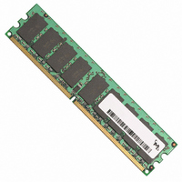
MODULE DDR2 512MB 240-DIMM
Manufacturer
Micron Technology Inc
Specifications of MT9HTF6472AY-40ED4
Memory Type
DDR2 SDRAM
Memory Size
512MB
Speed
400MT/s
Package / Case
240-DIMM
Main Category
DRAM Module
Sub-category
DDR2 SDRAM
Module Type
240RDIMM
Device Core Size
72b
Organization
64Mx72
Total Density
512MByte
Chip Density
512Mb
Access Time (max)
60ps
Maximum Clock Rate
400MHz
Operating Supply Voltage (typ)
1.8V
Operating Current
1.035A
Number Of Elements
9
Operating Supply Voltage (max)
1.9V
Operating Supply Voltage (min)
1.7V
Operating Temp Range
0C to 85C
Operating Temperature Classification
Commercial
Pin Count
240
Mounting
Socket
Lead Free Status / RoHS Status
Lead free / RoHS Compliant


pdf: 09005aef80e6f860, source: 09005aef80e5b799
HTF9C32_64_128x72AG_2.fm - Rev. C 6/05 EN
13. It is recommended that DQS be valid (HIGH or LOW) on or before the WRITE com-
14. The refresh period is 64ms. This equates to an average refresh rate of 7.8125µs. How-
15. Each byte lane has a corresponding DQS.
16. CK and CK# input slew rate must be ≥ 1V/ns (≥ 2 V/ns if measured differentially).
17. The data valid window is derived by achieving other specifications -
18.
19. MIN(
20.
21. READs and WRITEs with auto precharge are allowed to be issued before
22. V
23.
24. The minimum READ to internal PRECHARGE time. This parameter is only applicable
25. Operating frequency is only allowed to change during self refresh mode, precharge
26. ODT turn-on time
27. ODT turn-off time
28. This parameter has a two clock minimum requirement at any
29.
30.
31. No more than 4 bank ACTIVE commands may be issued in a given
mand. The case shown (DQS going from High-Z to logic LOW) applies when no
WRITEs were previously in progress on the bus. If a previous WRITE was in progress,
DQS could be HIGH during this time, depending on
ever, a REFRESH command must be asserted at least once every 70.3µs or
(MAX). To ensure all rows of all banks are properly refreshed, 8192 REFRESH com-
mands must be issued every 64ms.
t
tion to the clock duty cycle and a practical data valid window can be derived.
t
high time as provided to the device (i.e. This value can be greater than the minimum
specification limits for
period, less the half period jitter [
jitter due to cross talk [
t
device CK and CK# inputs.
satisfied since
SDRAM data sheet for more detail.
t
round to the next highest integer.
refers to the
ns with
clocks = 8 clocks.
when
standing,
matically delay the internal PRECHARGE command until
satisfied.
power-down mode, and system reset condition.
resistance begins to turn on. ODT turn-on time
tance is fully on. Both are measured from
ODT turn off time
sured from
t
prior to CK, CK# being removed in a system RESET condition.
t
t
DDR2 devices, regardless of the number of banks already open or closed.
DQSQ, and
JIT specification is currently TBD.
HP (MIN) is the lesser of
DAL = (nWR) + (
DELAY is calculated from
ISXR is equal to
RRD(min) restriction still applies. The
256MB, 512MB, 1GB (x72, SR, ECC) 240-Pin DDR2 SDRAM UDIMM
IL
/V
t
IH
CL,
t
RTP/(2*
t
DDR2 overshoot/undershoot. R
WR programmed to four clocks.
t
t
CH) refers to the smaller of the actual clock low time and the actual clock
RAS (MIN) has to be satisfied as well. The DDR2 SDRAM device will auto-
t
AOFD.
t
t
WR parameter stored in the MR[11,10,9]. Example: For -53E at
QH (
t
t
RAS lockout feature is supported in DDR2 SDRAM devices.
CK) > 1. If
t
IS and is used for CKE setup time during self refresh exit.
t
t
QH =
RP/
t
t
t
AOF (MAX) is when the bus is in high impedance. Both are mea-
AON (MIN) is when the device leaves high impedance and ODT
AOF (MIN) is when the device starts to turn off ODT resistance.
t
t
t
JIT(cross talk)] into the clock traces.
CK): For each of the terms above, if not already an integer,
CL and
t
HP -
t
RTP/(2*
t
36
t
IS +
CL minimum and
t
QHS). The data valid window derates in direct propor-
t
CH). For example,
t
CK +
t
JIT(HP)] of the clock source, and less the half period
t
CK) ≤ 1, then equation AL + BL/2 applies. Notwith-
t
Micron Technology, Inc., reserves the right to change products or specifications without notice.
CK refers to the application clock period; nWR
t
IH so that CKE registration LOW is guaranteed
t
EFER TO
FAW(min) parameter applies to all 8 bank
t
AOND.
t
DAL = 4 + (15 ns/3.75 ns) clocks = 4 +(4)
t
CH minimum actually applied to the
t
AON (MAX) is when the ODT resis-
the 256Mb, 512Mb, or 1Gb DDR2
t
CL and
t
DQSS.
©2003, 2004, 2005 Micron Technology, Inc. All rights reserved.
t
CH are = 50 percent of the
t
CK.
t
RAS (MIN) has been
t
FAW(min) period.
t
RAS (MIN) is
t
HP . (
t
CK = 3.75
Notes
t
CK/2),
t
RFC
Related parts for MT9HTF6472AY-40ED4
Image
Part Number
Description
Manufacturer
Datasheet
Request
R

Part Number:
Description:
IC SDRAM 64MBIT 133MHZ 54TSOP
Manufacturer:
Micron Technology Inc
Datasheet:

Part Number:
Description:
IC SDRAM 64MBIT 5.5NS 86TSOP
Manufacturer:
Micron Technology Inc
Datasheet:
Part Number:
Description:
IC SDRAM 64MBIT 200MHZ 86TSOP
Manufacturer:
Micron Technology Inc
Datasheet:
Part Number:
Description:
IC SDRAM 64MBIT 133MHZ 54TSOP
Manufacturer:
Micron Technology Inc
Datasheet:
Part Number:
Description:
IC SDRAM 128MBIT 133MHZ 54TSOP
Manufacturer:
Micron Technology Inc
Datasheet:

Part Number:
Description:
IC SDRAM 256MBIT 133MHZ 90VFBGA
Manufacturer:
Micron Technology Inc
Datasheet:
Part Number:
Description:
IC SDRAM 128MBIT 133MHZ 54TSOP
Manufacturer:
Micron Technology Inc
Datasheet:
Part Number:
Description:
IC SDRAM 256MBIT 133MHZ 54TSOP
Manufacturer:
Micron Technology Inc
Datasheet:

Part Number:
Description:
IC DDR SDRAM 512MBIT 6NS 66TSOP
Manufacturer:
Micron Technology Inc
Datasheet:
Part Number:
Description:
IC SDRAM 128MBIT 167MHZ 86TSOP
Manufacturer:
Micron Technology Inc
Datasheet:
Part Number:
Description:
IC SDRAM 128MBIT 143MHZ 86TSOP
Manufacturer:
Micron Technology Inc
Datasheet:

Part Number:
Description:
SDRAM 256M-BIT 1.8V 54-PIN VFBGA
Manufacturer:
Micron Technology Inc
Datasheet:
Part Number:
Description:
IC SDRAM 128MBIT 143MHZ 86TSOP
Manufacturer:
Micron Technology Inc
Datasheet:

Part Number:
Description:
IC SDRAM 128MBIT 125MHZ 54VFBGA
Manufacturer:
Micron Technology Inc
Datasheet:
Part Number:
Description:
IC SDRAM 128MBIT 125MHZ 54VFBGA
Manufacturer:
Micron Technology Inc
Datasheet: