KP-FSD3 Panduit Corp, KP-FSD3 Datasheet - Page 552
KP-FSD3
Manufacturer Part Number
KP-FSD3
Description
KIT FERRULE INS DIN AWG12-6
Manufacturer
Panduit Corp
Series
Pan-Term®r
Type
Ferrule Kitr
Datasheet
1.KP-FSD1.pdf
(1040 pages)
Specifications of KP-FSD3
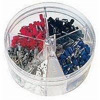
Kit Type
Ferrule - Wire End
Values
100 pcs - Assorted Insulated 12 ~ 6 AWG Ferrules
Kit Contents
50 Pieces Of FSD81-10, 20 Pieces Each Of FSD82-12 And FSD83-12, 10 Pieces Of FSD84-12
Mounting Method
Crimp
Where Used
To terminate stranded wire for insertion into terminal blocks
Lead Free Status / Rohs Status
Lead free / RoHS Compliant


Management
Identification
Accessories
Connectors
Connectors
& Write-On
Protection
Grounding
Pre-Printed
Cable Ties
Terminals
Permanent
Solutions
Overview
Steel Ties
Lockout/
& Safety
Stainless
Raceway
Abrasion
Labeling
Systems
Markers
Tagout
System
Surface
Wiring
Power
Labels
Index
Cable
Cable
D1.80
Duct
E5.
B1.
B2.
B3.
C1.
C2.
C3.
C4.
D1.
D2.
D3.
E1.
E2.
E3.
E4.
A.
F.
Crimping Guidelines for Panduit
Splices and Wire Joints
1. Select the proper Panduit terminal for the application and wire size used
• Ring terminals are used for high vibration and grounding applications
• Fork terminals are used for static (non-vibration) applications
• Disconnects are used for applications that require quick connection of wires
• Splices and wire joints are used to join wires together
2. Strip wire to the proper length as specified on:
• Panduit product packaging label
• Packaging instructions included with the Panduit product
• Or if no packaging instructions are available, plan your strip length so that 1/32'' of wire can be seen protruding through
3. Select the proper crimp tool to be used
• Use crimping tools that provide a UL Listed and/or CSA Certified electrical termination, to assure a safe and
• Panduit terminals are UL Listed and CSA Certified when crimped with Panduit plier type crimping tool or with the preferred
4. Select the proper crimp pocket for the terminals and wire size you are using
• Panduit crimping tools simplify this process with color-coded crimp pockets. The yellow, blue, and red pockets are
5. Perform the electrical crimp for the plier type tool
Insulated Terminals and Disconnects
A. Locate terminal in appropriate size color-coded crimp die
B. Rotate terminal so tongue is level with crimp die.
C. Insert properly stripped wire into terminal until a minimum of
D. Squeeze tool handles firmly to perform the electrical crimp.
E. Provide second crimp on the flared portion of the insulation housing to
without the use of tools
the tongue end of the terminal barrel
reliable connection
Contour Crimp
specifically designed for the industry standard barrel sizes, each with a specific color code.
Order number of pieces required, in multiples of Standard Package Quantity.
pocket with tool centered on insulation sleeve.
(See Note 1, page D1.82)
1/32'' of wire extends beyond the terminal barrel.
(See Note 2, page D1.82)
close the insulation as shown. Caution: When using plier type crimping
tools, do not squeeze as firmly as you did for the electrical crimp.
(See Note 3, page D1.82)
™
Controlled Cycle Crimping Tool specified on the packaging label
Plier Type
Crimping Tool
ELECTRICAL SOLUTIONS
®
Pan-Term
Contour Crimp
Controlled Cycle
Crimping Tool
Step A
®
Terminals, Disconnects,
Step E
™
Step B
Complete Crimp
Prime items appear in BOLD.
Steps C and D