KP-FSD3 Panduit Corp, KP-FSD3 Datasheet - Page 186
KP-FSD3
Manufacturer Part Number
KP-FSD3
Description
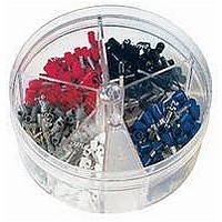
KIT FERRULE INS DIN AWG12-6
Manufacturer
Panduit Corp
Series
Pan-Term®r
Type
Ferrule Kitr
Datasheet
1.KP-FSD1.pdf
(1040 pages)
Specifications of KP-FSD3
Kit Type
Ferrule - Wire End
Values
100 pcs - Assorted Insulated 12 ~ 6 AWG Ferrules
Kit Contents
50 Pieces Of FSD81-10, 20 Pieces Each Of FSD82-12 And FSD83-12, 10 Pieces Of FSD84-12
Mounting Method
Crimp
Where Used
To terminate stranded wire for insertion into terminal blocks
Lead Free Status / Rohs Status
Lead free / RoHS Compliant


Management
Identification
Accessories
Connectors
Connectors
& Write-On
Protection
Grounding
Pre-Printed
Cable Ties
Terminals
Permanent
Solutions
Overview
Steel Ties
Lockout/
& Safety
Stainless
Raceway
Abrasion
Labeling
Systems
Markers
Tagout
System
Surface
Wiring
Power
Labels
Index
Cable
Cable
Duct
B2.34
E5.
B1.
B2.
B3.
C1.
C2.
C3.
C4.
D1.
D2.
D3.
E1.
E2.
E3.
E4.
A.
F.
Adhesive Backed
Push Mount
• Route and secure cords and cables
• Convenient releasable latch
• Available in six sizes with releasable latch
Part Number
LWC19-A-C
LWC19-A-C14
LWC19-A-C20
LWC25-A-C
LWC25-A-C14
LWC25-A-C20
LWC38-A-C
LWC38-A-C14
LWC38-A-C20
LWC50-A-L
LWC50-A-L14
LWC50-A-L20
LWC75-A-L
LWC75-A-L14
LWC75-A-L20
LWC100-A-L
LWC100-A-L14
LWC100-A-L20
LWC19-H25-C
LWC19-H25-C14
LWC25-H25-C
LWC25-H25-C14
LWC25-H25-C20
LWC38-H25-C
LWC38-H25-C14
LWC38-H25-C20
LWC50-H25-L
LWC50-H25-L14
LWC50-H25-L20
LWC75-H25-L
LWC75-H25-L14
LWC75-H25-L20
LWC100-H25-L
LWC100-H25-L14
LWC100-H25-L20
Order number of pieces required, in multiples of Standard Package Quantity.
Latching Wire Clips
Max. Bundle
0.19
0.19
0.19
0.25
0.25
0.25
0.38
0.38
0.38
0.50
0.50
0.50
0.75
0.75
0.75
1.00
1.00
1.00
0.19
0.19
0.25
0.25
0.25
0.38
0.38
0.38
0.50
0.50
0.50
0.75
0.75
0.75
1.00
1.00
1.00
In.
Diameter
12.7
12.7
12.7
19.1
19.1
19.1
25.4
25.4
25.4
12.7
12.7
12.7
19.1
19.1
19.1
25.4
25.4
25.4
mm
4.8
4.8
4.8
6.4
6.4
6.4
9.5
9.5
9.5
4.8
4.8
6.4
6.4
6.4
9.5
9.5
9.5
0.85
0.85
0.85
0.88
0.88
0.88
1.00
1.00
1.00
1.26
1.26
1.26
1.48
1.48
1.48
2.21
2.21
2.21
0.85
0.85
0.86
0.86
0.86
0.94
0.94
0.94
1.25
1.25
1.25
1.45
1.45
1.45
1.89
1.89
1.89
In.
Length
A
21.6
21.6
21.6
22.2
22.2
22.2
25.4
25.4
25.4
32.0
32.0
32.0
37.6
37.6
37.6
56.1
56.1
56.1
21.6
21.6
21.8
21.8
21.8
23.9
23.9
23.9
31.8
31.8
31.8
36.8
36.8
36.8
47.9
47.9
47.9
B
mm
ELECTRICAL SOLUTIONS
LWC * * -A
A
0.61
0.61
0.61
1.00
1.00
1.00
1.00
1.00
1.00
1.00
1.00
1.00
1.24
1.24
1.24
1.97
1.97
1.97
0.51
0.51
0.58
0.58
0.58
0.58
0.58
0.58
0.76
0.76
0.76
0.87
0.87
0.87
0.99
0.99
0.99
In.
Width
B
15.5
15.5
15.5
25.4
25.4
25.4
25.4
25.4
25.4
25.4
25.4
25.4
31.5
31.5
31.5
50.0
50.0
50.0
12.8
12.8
14.7
14.7
14.7
14.7
14.7
14.7
19.3
19.3
19.3
22.1
22.1
22.1
25.2
25.2
25.2
mm
• Push barb parts are for use with a max panel thickness of
• For indoor use only
• Material: Nylon 6.6
0.11" (2.7mm) and a hole diameter of .22" (5.6mm)
C
0.39
0.39
0.39
0.45
0.45
0.45
0.56
0.56
0.56
0.67
0.67
0.67
0.90
0.90
0.90
1.26
1.26
1.26
0.41
0.41
0.47
0.47
0.47
0.57
0.57
0.57
0.78
0.78
0.78
0.97
0.97
0.97
1.30
1.30
1.30
In.
Height
C
LWC * * -H25
11.4
11.4
11.4
14.2
14.2
14.2
17.0
17.0
17.0
22.9
22.9
22.9
32.0
32.0
32.0
10.4
10.4
11.9
11.9
11.9
14.5
14.5
14.5
19.8
19.8
19.8
24.7
24.7
24.7
33.0
33.0
33.0
mm
9.9
9.9
9.9
Natural
Natural
Natural
Natural
Natural
Natural
Natural
Natural
Natural
Natural
Natural
Natural
Color
Black
Black
Black
Black
Black
Black
Black
Black
Black
Black
Black
Gray
Gray
Gray
Gray
Gray
Gray
Gray
Gray
Gray
Gray
Gray
Gray
C
Push Barb
Mounting
Adhesive
Prime items appear in BOLD.
Method
Rubber
Pkg.
Std.
Qty.
100
100
100
100
100
100
100
100
100
100
100
100
100
100
100
100
100
50
50
50
50
50
50
50
50
50
50
50
50
50
50
50
50
50
50
1000
1000
1000
1000
1000
1000
1000
1000
1000
1000
1000
1000
1000
1000
1000
1000
1000
Std.
Ctn.
Qty.
500
500
500
500
500
500
500
500
500
500
500
500
500
500
500
500
500
500