KP-FSD3 Panduit Corp, KP-FSD3 Datasheet - Page 505
KP-FSD3
Manufacturer Part Number
KP-FSD3
Description
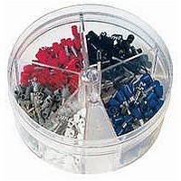
KIT FERRULE INS DIN AWG12-6
Manufacturer
Panduit Corp
Series
Pan-Term®r
Type
Ferrule Kitr
Datasheet
1.KP-FSD1.pdf
(1040 pages)
Specifications of KP-FSD3
Kit Type
Ferrule - Wire End
Values
100 pcs - Assorted Insulated 12 ~ 6 AWG Ferrules
Kit Contents
50 Pieces Of FSD81-10, 20 Pieces Each Of FSD82-12 And FSD83-12, 10 Pieces Of FSD84-12
Mounting Method
Crimp
Where Used
To terminate stranded wire for insertion into terminal blocks
Lead Free Status / Rohs Status
Lead free / RoHS Compliant


Type
PM = Pan-Term
Part Number System for Pan-Term
Metric Ring Terminal, Nylon Insulated – Funnel Entry
Type PMNF-R
• Ring tongue design assures a secure connection in high vibration
• Metal insulation grip sleeve crimps to wire insulation, providing
PM
applications
protection to the crimp joint during high vibration applications
Metric
C
L
®
Insulation
N = Nylon
NF = Nylon
V = Vinyl
V
Funnel
W
Wire Range
1 = 0.5 – 1.0mm
2 = 1.5 – 2.5mm
6 = 4.0 – 6.0mm
(22 – 18 AWG)
(16 – 14 AWG)
(12 – 10 AWG)
1
For crimping tool information, see pages D1.84 and D1.88.
Part Number
PMNF1-3R-C
PMNF1-4R-C
PMNF1-5R-C
PMNF1-6R-C
PMNF2-3R-C
PMNF2-4R-C
PMNF2-5R-C
PMNF2-6R-L
PMNF6-3R-L
PMNF6-4R-L
PMNF6-5R-L
PMNF6-6R-L
PMNF6-8R-L
For technical assistance in the U.S., call 866-405-6654 (outside the U.S., see inside back cover for directory)
2
2
2
Stud Size
3 = M3 (#6)
4 = M4 (#8)
5 = M5 (#10)
6 = M6 (1/4)
8 = M8 (5/16)
®
0.5 – 1.0
1.5 – 2.5
4.0 – 6.0
Range
(mm
Wire
ELECTRICAL SOLUTIONS
Metric Terminals
3
2
)
Yellow
Color
Code
Red
Blue
Tongue Configuration
R = Ring
F = Fork
• Internal barrel serrations assure good wire contact and maximum
• Maximum insulation temperature 221°F (105°C)
• Rated up to 600 V
(mm)
Max.
3.76
3.76
3.76
3.76
4.11
4.11
4.11
4.11
5.94
5.94
5.94
5.94
5.94
tensile strength
Ins.
R
Stud
Size
M3
M4
M5
M6
M3
M4
M5
M6
M3
M4
M5
M6
M8
19.3
21.6
21.8
26.7
19.4
21.8
22.4
26.5
26.7
27.4
27.4
30.2
31.5
L
Figure Dimensions
B = Butted
Special Configuration
(mm)
10.9
10.9
10.9
13.2
5.8
7.9
8.9
5.9
7.9
8.9
5.8
7.9
9.7
W
Seam
B
10.7
10.9
10.9
5.3
6.4
6.4
9.7
4.8
7.4
7.4
9.1
9.1
9.1
C
Recommended
Installation
CT-1550,
CT-1550,
CT-1550,
CT-2500
CT-2500
CT-2500
Tool
Std. Pkg. Size
X = 10
E = 20
Q = 25
L = 50
C = 100
Pkg.
Std.
Qty.
C
100
100
100
100
100
100
100
50
50
50
50
50
50
Std.
Ctn.
Qty.
500
500
500
500
500
500
500
500
250
250
250
250
250
D1.33
Management
Identification
Accessories
Connectors
Connectors
Grounding
Pre-Printed
& Write-On
Protection
Permanent
Solutions
Cable Ties
Terminals
Lockout/
Overview
Steel Ties
& Safety
Stainless
Raceway
Abrasion
Labeling
Systems
Surface
Markers
Tagout
System
Wiring
Labels
Power
Cable
Cable
Index
Duct
E5.
B1.
B2.
B3.
D1.
D2.
D3.
C1.
C2.
C3.
C4.
E1.
E2.
E3.
E4.
A.
F.