FDMF8705 Fairchild Semiconductor, FDMF8705 Datasheet
FDMF8705
Specifications of FDMF8705


Related parts for FDMF8705


FDMF8705 Summary of contents
Page 1
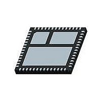
... Fairchild Semiconductor Corporation FDMF8705 Rev. C General Description The FDMF8705 is a fully optimized integrated 12V Driver plus MOSFET power stage solution for high current synchronous buck DC-DC applications. The device integrates a driver IC and two Power MOSFETs into a space saving, 8mm x 8mm, 56-pin Power88™ ...
Page 2
... Functional Block Diagram DISB PWM Pin Configuration PWM DISB CGND VSWH VSWH VSWH VSWH VSWH VSWH VSWH VSWH FDMF8705 Rev. C BOOT VCIN 1.2 2.2 VCIN CGND Figure 2. Functional Block Diagram (CGND) (VIN (VSWH Figure 3. Power88 56L Bottom View 2 HDRV VIN VSWH 1 ...
Page 3
... Parameter Control Circuit Supply Current Undervoltage lockout threshold PWM Input High Voltage FDMF8705 Rev Ground. Ground return for driver IC. No connect IC Supply. +12V chip bias power. Bypass with a 1µF ceramic capacitor. Bootstrap Supply Input. Provides voltage supply to high-side MOSFET driver. Connect bootstrap capacitor ...
Page 4
... Note 1: Package power dissipation based on 4 layer, 2 square inch, 2 oz. copper pad. R thermal resistance with PCB temperature referenced at VSWH pin. Note 2: When combined with controller, driver UVLO must be less than that of controller. Note 3: t refers to HIGH-to-LOW transition, t PDL(LDRV/HRDV) FDMF8705 Rev Symbol Conditions V IL(PWM) ...
Page 5
... Figure 6. Power Loss vs. Switching Frequency 1.10 1.08 1.05 1. 12V 1. 1.3V OUT I = 18A OUT 0. 0.68uH f = 300KHz SW 0. Driver Supply Voltage, V Figure 8. Power Loss vs. Driver Supply Voltage FDMF8705 Rev 12V 1.3V OUT 0.68uH 100 125 150 Figure 5. Module Power Loss vs. Output Current 1.10 1.05 1.00 V 0.95 ...
Page 6
... Temperature, Figure 12. Supply Current vs. Temperature 2 1.9 1.8 1.7 1 1.5 1 Driver Supply Voltage, V Figure 14. DISB Threshold Voltage vs. Driver Supply Voltage FDMF8705 Rev. C 4.4 4.2 4.0 3.8 3.6 3.4 3.2 3.0 2.8 6 0.7 0.8 0.9 1 CIN 100 125 150 ...
Page 7
... Transient Duration, nsec Figure 18. VSWH vs. Transient Duration PWM HDRV V = 12V LDRV 12V CIN V = 1.3V OUT f = 500KHz sw VSWH OUT Figure 20. Switching Waveform at Iout = 0A FDMF8705 Rev. C 3.0 2.7 2.4 2.1 1.8 1 300 400 500 0 Figure 19. Boot to Ground Voltage vs. Transient Duration ...
Page 8
... PWM HDRV LDRV VSWH Figure 22. Switching Waveform (Rising edge) FDMF8705 Rev. C PWM V = 12V IN HDRV V = 12V CIN V = 1.3V OUT f = 500KHz LDRV 18A OUT VSWH Figure 23. Switching Waveform (Falling Edge 12V 12V CIN V = 1.3V OUT f = 500KHz 18A OUT www.fairchildsemi.com ...
Page 9
... Description of Operation Circuit Description The FDMF8705 is a driver plus FET module optimized for synchronous buck converter topology. A single PWM input signal is all that is required to properly drive the high-side and the low-side MOSFETs. Each part is capable of driving speeds up to 500KHz. Low-Side Driver ...
Page 10
... GND Application Information Supply Capacitor Selection For the supply input (VCIN) of the FDMF8705, a local ceramic bypass capacitor is recommended to reduce the noise and to supply the peak current. Use at least a 1µF, X7R or X5R capac- itor. Keep this capacitor close to the FDMF8705 VCIN and CGND pins ...
Page 11
... Output inductor location should be as close as possible to the FDMF8705 for lower power loss due to copper trace. 4. Place ceramic bypass capacitor and boot capacitor as close to VCIN and BOOT pin of FDMF8705 in order to supply stable power. Routing width and length should also be considered. , VSWH ...
Page 12
... Dimensional Outline and Pad layout FDMF8705 Rev. C (DATUM A) Bayan Lepas FIZ 11900, Penang, Malaysia 12 www.fairchildsemi.com ...
Page 13
... TRADEMARKS The following are registered and unregistered trademarks Fairchild Semiconductor owns or is authorized to use and is not intended exhaustive list of all such trademarks. ® ACEx Across the board. Around the world.™ ActiveArray™ Bottomless™ Build it Now™ CoolFET™ CROSSVOLT™ ...