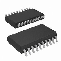
ISL6755AAZA-T Intersil, ISL6755AAZA-T Datasheet - Page 10

ISL6755AAZA-T
Manufacturer Part Number
ISL6755AAZA-T
Description
IC CTRLR PWM FULL-BRDG 20-QSOP
Manufacturer
Intersil
Datasheet
1.ISL6755AAZA.pdf
(17 pages)
Specifications of ISL6755AAZA-T
Pwm Type
Voltage/Current Mode
Number Of Outputs
4
Frequency - Max
2MHz
Duty Cycle
100%
Voltage - Supply
9 V ~ 16 V
Buck
No
Boost
No
Flyback
No
Inverting
No
Doubler
No
Divider
No
Cuk
No
Isolated
No
Operating Temperature
-40°C ~ 105°C
Package / Case
20-QSOP
Frequency-max
2MHz
Lead Free Status / RoHS Status
Lead free / RoHS Compliant
The average current signal on I
provided that the output inductor current is continuous (CCM
operation). Once the inductor current becomes
discontinuous (DCM operation), I
peak inductor current rather than the average current. This
occurs because the sample and hold circuitry is active only
during the on time of the switching cycle. It is unable to
detect when the inductor current reaches zero during the off
time.
If average overcurrent limit is desired, I
with either of the available error amplifiers of the ISL6755.
Typically I
achieve the desired amplitude. The resulting signal is input
to the current error amplifier (IEA). The IEA is similar to the
voltage EA found in most PWM controllers, except it cannot
source current. Instead, VERR has a separate internal 1mA
pull-up current source.
Configure the IEA as an integrating (Type I) amplifier using
the internal 0.6V reference. The voltage applied at FBx is
integrated against the 0.6V reference. The resulting signal,
VERR, is applied to the PWM comparator where it is
compared to the sawtooth voltage on RAMP. If FBx is less
than 0.6V, the IEA will be open loop (can’t source current),
VERR will be at a level determined by the voltage loop, and
the duty cycle is unaffected. As the output load increases,
IOUT will increase, and the voltage applied to FB will
increase until it reaches 0.6V. At this point the IEA will
reduce VERR as required to maintain the output current at
the level that corresponds to the 0.6V reference. When the
output current again drops below the average current limit
threshold, the IEA returns to an open loop condition, and the
duty cycle is again controlled by the voltage loop.
The average current control loop behaves much the same
as the voltage control loop found in typical power supplies
except it regulates current rather than voltage.
CHANNEL 1 (YELLOW): OUTLL
CHANNEL 3 (BLUE): CS
FIGURE 6. DYNAMIC BEHAVIOR OF CS vs IOUT
OUT
is divided down and filtered as required to
10
OUT
OUT
CHANNEL 2 (RED): OUTLR
CHANNEL 4 (GREEN): IOUT
remains accurate
represents 1/2 the
OUT
may be used
ISL6755
The EA available on the ISL6755 may also be used as the
voltage EA for the voltage feedback control loop rather than
the current EA as described above. An external op-amp may
be used as either the current or voltage EA providing the
circuit is not allowed to source current into VERR. The
external EA must only sink current, which may be
accomplished by adding a diode in series with its output.
The 4x gain of the sample and hold buffer allows a range of
150mV to 1000mV peak on the CS signal, depending on the
resistor divider placed on I
average current loop is determined by the integrating current
EA compensation and the divider on I
The current EA cross-over frequency, assuming R6 >>
(R4||R5), is:
where f
with R4 may be used to provide a double-pole roll-off.
The average current loop bandwidth is normally set to be
much less than the switching frequency, typically less than
5kHz and often as slow as a few hundred hertz or less. This
is especially useful if the application experiences large
surges. The average current loop can be set to the steady
state overcurrent threshold and have a time response that is
longer than the required transient. The peak current limit can
be set higher than the expected transient so that it does not
interfere with the transient, but still protects for short-term
larger faults. In essence a 2-stage overcurrent response is
possible.
f
CO
FIGURE 7. AVERAGE OVERCURRENT IMPLEMENTATION
=
---------------------------------- -
2π R6 C10
150 - 1000 mV
CO
⋅
is the cross-over frequency. A capacitor in parallel
1
⋅
C10
R6
Hz
OUT
R5
R4
. The overall bandwidth of the
10
1
2
3
4
5
6
7
8
9
VERR
FB1
CS
IOUT
0.6V
ISL6755
S&H
OUT
4x
+
-
.
September 29, 2008
20
19
18
17
16
15
14
13
12
11
VREF
SS
VDD
OUTLL
OUTLR
OUTUL
OUTUR
N/C
GND
GND
FN6442.1
(EQ. 7)


