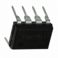
FAN7711N Fairchild Semiconductor, FAN7711N Datasheet - Page 14

FAN7711N
Manufacturer Part Number
FAN7711N
Description
IC BALLAST CONTROL HV 8-DIP
Manufacturer
Fairchild Semiconductor
Type
Ballast Controllerr
Specifications of FAN7711N
Frequency
48.7 ~ 57.3 kHz
Current - Supply
3.2mA
Current - Output
650mA
Operating Temperature
-25°C ~ 125°C
Package / Case
8-DIP (0.300", 7.62mm)
Switching Frequency
95 KHz
Operating Temperature Range
- 25 C to + 125 C
Mounting Style
Through Hole
Lead Free Status / RoHS Status
Lead free / RoHS Compliant
Voltage - Supply
-
Lead Free Status / Rohs Status
Lead free / RoHS Compliant
Available stocks
Company
Part Number
Manufacturer
Quantity
Price
Company:
Part Number:
FAN7711N
Manufacturer:
FSC
Quantity:
15 000
FAN7711 Rev. 1.0.3
© 2007 Fairchild Semiconductor Corporation
2. Current Supplied by Charge Pump
For the IC supply, the charge pump method is used in
Figure 29. Since C
output, the supplied current by C
determined by the output voltage of the half-bridge.
When the half-bridge output shows rising slope, C
charged and the charging current is supplied to the IC.
The current can be estimated as:
where DT is the dead time and dV/dt is the voltage
variation of the half-bridge output.
When the half-bridge shows falling slope, C
discharged through Dp2. Total supplied current, I
the IC during switching period, t, is:
From Equation 19, the average current, I
the IC is obtained by:
For the stable operation, I
required current. If I
residual current flows through the shunt regulator
implemented on the chip, which can cause unwanted
heat generation. Therefore, C
considering stable operation and thermal generation.
For example, if C
is ~7.8mA; it is enough current for stable operation.
V
DC
I
dp1
I
avg
Figure 29. Charge Pump Operation
C
CP
=
Charging mode
I
total
DT:dead time
t
I
Dp2
total
I
Dp1
CP
=
I
=
dp1
C
= ⋅
C
=0.5nF, V
avg
CP
CP
I DT
CP
dV
dt
To V
exceeds the required current, the
t
⋅
f=1/t
is connected to the half-bridge
V
C
DC
VDD
≈
DD
=
avg
C
C
=
CP
DC
CP
C
must be higher than the
CP
V
=311V, and f=50kHz, I
⋅
DT
V
DC
CP
DC
⋅
V
DC
Discharging mode
C
must be selected
CP
CP
⋅
f
FAN7711 Rev. 1.00
Half-bridge output
avg
Dp2
to the IC is
I
Dp1
dp1
, supplied to
=0
(EQ 18)
(EQ 19)
(EQ 20)
To V
total
C
CP
CP
VDD
DD
, to
avg
is
is
14
3. Lamp Turn-on Time
The turn-on time of the lamp is determined by supply
build-up time t
where t
IC's supply voltage exceeds V
restart, the IC operates in preheating mode. This
operation continues until CPH pin's voltage reaches ~3V.
In this mode, CPH capacitor is charged by I
as depicted in Figure 30. The preheating time is
achieved by calculating:
The preheating time is related to lamp life (especially
filament); therefore, the characteristics of a given lamp
should be considered when choosing the time.
Compared to the preheating time, it is almost impossible
to exactly predict the ignition time, whose definition is the
time from the end of the preheating time to ignition. In
general, the lamp ignites during the ignition mode.
Therefore, assume that the maximum ignition time is the
same as the duration of ignition mode, from 3V until CPH
reaches 5V. Thus, ignition time can be defined as:
Note that, at ignition mode, CPH is charged by I
is six times larger than I
time is approximately:
VDD Build-Time + Preheating Time + Ignition Time =
CPH
start
t
ignition
has been obtained by Equation 17. When the
Figure 30. Preheating Timer
t
ignition
=
I
start
PH
(
5 3
−
, preheating time, and ignition time;
=
t
preheat
(
)
5 3
CPH
I
−
IG
PH
=
)
CPH
=
3
. Consequently, total turn-on
I
IG
2
CPH
I
PH
CPH
V
RT
CPH
GND
DDTH(ST+)
I
DD
=
IG
2
CPH
[
Sec
I
IG
FAN7711 Rev. 1.00
.]
after turn-on or
www.fairchildsemi.com
PH
(EQ 21)
(EQ 23)
IG
(EQ 22)
current,
, which


