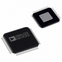
AD8384ASVZ Analog Devices Inc, AD8384ASVZ Datasheet - Page 3

AD8384ASVZ
Manufacturer Part Number
AD8384ASVZ
Description
IC DRIVER LCD 6CH 10BIT 80-TQFP
Manufacturer
Analog Devices Inc
Series
DecDriver™r
Datasheet
1.AD8384ASVZ.pdf
(24 pages)
Specifications of AD8384ASVZ
Display Type
LCD
Interface
3-Wire Serial
Current - Supply
40mA
Voltage - Supply
9 V ~ 18 V
Operating Temperature
0°C ~ 85°C
Mounting Type
Surface Mount
Package / Case
80-TQFP Exposed Pad, 80-eTQFP, 80-HTQFP, 80-VQFP
Lead Free Status / RoHS Status
Lead free / RoHS Compliant
Configuration
-
Digits Or Characters
-
Available stocks
Company
Part Number
Manufacturer
Quantity
Price
Company:
Part Number:
AD8384ASVZ
Manufacturer:
Analog Devices Inc
Quantity:
10 000
SPECIFICATIONS
DecDriver
Table 1. @ 25°C, AVCC = 15.5 V, DVCC = 3.3 V, T
unless otherwise noted
Parameter
VIDEO DC PERFORMANCE
VIDEO OUTPUT DYNAMIC PERFORMANCE
VIDEO OUTPUT CHARACTERISTICS
REFERENCE INPUTS
RESOLUTION
1
2
3
4
5
VDE = differential error voltage; VCME = common-mode error voltage; VFS = full-scale output voltage = 2 × (VRH – VRL). See the
Measured differentially on two outputs as CLK and DB(0:9) are driven and STSQ and XFR are held LOW.
Measured differentially on two outputs as the other four are transitioning by 5 V. Measured for both states of INV.
Measured from 50% of rising CLK edge to 50% of output change. Measurement is made for both states of INV.
Measured from 50% of rising CLK edge to 50% of output change. Refer to Figure 7 for the definition.
VDE
VCME
Data Switching Slew Rate
Invert Switching Slew Rate
Data Switching Settling Time to 1%
Data Switching Settling Time to 0.25%
Invert Switching Settling Time to 1%
Invert Switching Settling Time to 0.25%
Invert Switching Overshoot
CLK and Data Feedthrough
All-Hostile Crosstalk
DAC Transition Glitch Energy
Output Voltage Swing
Output Voltage—Grounded Mode
Data Switching Delay: t
INV Switching Delay: t
Output Current
Output Resistance
V1 Range
V2 Range
V1 Input Current
V2 Input Current
VRL Range
VRH Range
(VRH–VRL) Range
VRH Input Resistance
VRL Bias Current
VRH Input Current
Coding
Amplitude
Glitch Duration
3
10
9
1
5
4
2
DAC Code 450 to 800
DAC Code 450 to 800
T
VFS = 2(VRH – VRL)
Binary
Conditions
T
20% to 80%
20% to 80%
V
V
V
DAC Code 511 to 512
AVCC – VOH, VOL – AGND
50 % of VIDx
50 % of VIDx
V2 ≥ (V1-0.25V)
V2 ≥ (V1-0.25V)
VRH ≥ VRL
VRH ≥ VRL
To VRL
A MIN
A MIN
O
O
O
= 10 V Step
= 10 V Step
= 10 V Step
A MIN
to T
to T
= 0°C, T
A MAX
A MAX
Rev. 0 | Page 3 of 24
, V
O
A MAX
= 5 V Step, C
= 85°C, VRH = 9.5 V, VRL = V1 = V2 = 7 V,
L
= 150 pF
Min
–7.5
–3.5
10
13
5.25
5.25
V1 – 0.5
VRL
0
10
Accuracy
Typ
460
560
19
30
75
250
100
10
10
30
0.3
1.1
0.25
12
15
100
22
–3
–14
20
–0.2
125
section.
Max
+7.5
+3.5
24
50
120
500
200
1.3
14
17
AVCC – 4
AVCC – 4
AVCC – 1.3
AVCC
2.75
AD8384
V/µs
V/µs
ns
ns
ns
ns
mV p-p
mV p-p
ns
ns
ns
V
V
Unit
mV
mV
mV
nV-s
V
V
mA
Ω
V
V
µA
µA
V
kΩ
µA
µA
Bits


