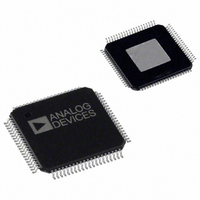
AD8384ASVZ Analog Devices Inc, AD8384ASVZ Datasheet - Page 18

AD8384ASVZ
Manufacturer Part Number
AD8384ASVZ
Description
IC DRIVER LCD 6CH 10BIT 80-TQFP
Manufacturer
Analog Devices Inc
Series
DecDriver™r
Datasheet
1.AD8384ASVZ.pdf
(24 pages)
Specifications of AD8384ASVZ
Display Type
LCD
Interface
3-Wire Serial
Current - Supply
40mA
Voltage - Supply
9 V ~ 18 V
Operating Temperature
0°C ~ 85°C
Mounting Type
Surface Mount
Package / Case
80-TQFP Exposed Pad, 80-eTQFP, 80-HTQFP, 80-VQFP
Lead Free Status / RoHS Status
Lead free / RoHS Compliant
Configuration
-
Digits Or Characters
-
Available stocks
Company
Part Number
Manufacturer
Quantity
Price
Company:
Part Number:
AD8384ASVZ
Manufacturer:
Analog Devices Inc
Quantity:
10 000
AD8384
VBIAS GENERATION—V1, V2 INPUT PIN
FUNCTIONALITY
In order to avoid image flicker, a symmetrical ac voltage is
required and a bias voltage of approximately 1 V minimum
must be maintained across the pixels of HTPS LCDs. The
AD8384 provides two methods of maintaining this bias voltage.
Internal Bias Voltage Generation
Standard systems that internally generate the bias voltage
reserve the upper-most code range for the bias voltage, and use
the remaining code range to encode the video for gamma
correction. In these systems, a high degree of ac symmetry is
guaranteed by the AD8384.
The V1 and V2 inputs in these systems are tied together and are
normally connected to VCOM, as shown in Figure 17.
External Bias Voltage Generation
In systems that require improved brightness resolution and
higher accuracy, the V1 and V2 inputs, connected to external
voltage references, provide the necessary bias voltage (VBIAS)
while allowing the full code range to be used for gamma
correction.
To ensure a symmetrical ac voltage at the outputs of the
AD8384, VBIAS must remain constant for both states of INV.
Therefore, V1 and V2 are defined as
VCOM
Figure 17. V1, V2 Connection and Transfer Function
V2
V1
AD8384
in a Typical Standard System
V1 = VCOM – VBIAS
V2 = VCOM + VBIAS
VCOM
VFS = 5V
VFS = 5V
VBIAS = 1V
VBIAS = 1V
RESERVED
820
RANGE
CODE
1023
Rev. 0 | Page 18 of 24
APPLICATIONS CIRCUIT
The circuit in Figure 18 ensures VBIAS symmetry to within
1 mV with a minimum component count. Bypass capacitors are
not shown for clarity.
Note from the curve in Figure 20 that the AD8132 (Figure 18)
typically produces a symmetrical output at 85°C when its
supply, (V+) – (V–), is at 7.2 V.
VCOM = 7V
Figure 20. Typical Asymmetry at the Outputs of the AD8132 vs. Its Power
Figure 19. AD8384 Transfer Function in a Typical High Accuracy System
–1.25
–2.50
–3.75
–5.00
–6.25
–7.50
–8.75
8.75
7.50
6.25
5.00
3.75
2.50
1.25
0.00
R2 = 1kΩ
R1 = 6kΩ
5.7
Figure 18. External VBIAS Generator with the AD8132
6.2
VCOM
6.7
1
2
8
Supply for the Application Circuit
V2
V1
–IN
V COM
+IN
DVCC = 3.3V
7.2
AVCC = 15.5V
AD8132
T
V+
V–
A
VFS = 4V
VFS = 4V
3
6
7.7
= 85°C
[V+] – [V–] (V)
VZ = 5.1V
5
4
8.2
VBIAS = 1V
VBIAS = 1V
8.7
V2 = 8V
V1 = 6V
9.2
T
A
1023
= 25°C
9.7
V2
V1
AD8384
10.2 10.7


