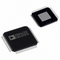
AD8384ASVZ Analog Devices Inc, AD8384ASVZ Datasheet

AD8384ASVZ
Specifications of AD8384ASVZ
Available stocks
Related parts for AD8384ASVZ
AD8384ASVZ Summary of contents
Page 1
PRODUCT FEATURES High accuracy, high resolution voltage outputs 10-bit input resolution Laser trimmed outputs Fast settling, high voltage drive 30 ns settling time to 0.25% into a 150 pF load Slew rate 460 V/µs Outputs to within 1 ...
Page 2
AD8384 TABLE OF CONTENTS Specifications..................................................................................... 3 DecDriver ...................................................................................... 3 Level Shifters ................................................................................. 5 Level Shifting Edge Detector ...................................................... 5 Serial Interface .............................................................................. 6 Power Supplies .............................................................................. 7 Operating Temperature ............................................................... 7 Absolute Maximum Ratings............................................................ 8 Maximum Power Dissipation ..................................................... 8 ...
Page 3
SPECIFICATIONS DecDriver Table 1. @ 25°C, AVCC = 15.5 V, DVCC = 3 unless otherwise noted Parameter 1 VIDEO DC PERFORMANCE VDE VCME VIDEO OUTPUT DYNAMIC PERFORMANCE Data Switching Slew Rate Invert Switching Slew Rate Data Switching Settling ...
Page 4
AD8384 DecDriver (continued) Parameter DIGITAL INPUT CHARACTERISTICS Max. Input Data Update Rate CLK to Data Setup Time CLK to STSQ Setup Time CLK to XFR Setup Time CLK to Data Hold Time ...
Page 5
LEVEL SHIFTERS Table 2. @ 25°C, AVCC = 15.5 V, DVCC = 3 unless otherwise noted Parameter LEVEL SHIFTER LOGIC INPUTS LEVEL SHIFTER OUTPUTS V OH ...
Page 6
AD8384 SERIAL INTERFACE Table 4. @ 25°C, AVCC = 15.5 V, DVCC = 3 Parameter SERIAL DAC REFERENCE INPUTS SVRH Range SVRL Range SVFS Range SVRH Input Current SVRL Input Current SVRH Input Resistance SERIAL DAC ACCURACY DNL ...
Page 7
POWER SUPPLIES Table 5. @ 25°C, AVCC = 15.5 V, DVCC = 3 Parameter DVCC, Operating Range DVCC, Quiescent Current AVCC Operating Range Total AVCC Quiescent Current OPERATING TEMPERATURE Parameter 7 Ambient Temperature Range Ambient Temperature ...
Page 8
AD8384 ABSOLUTE MAXIMUM RATINGS 9 Table 6. AD8384 Stress Ratings Parameter Supply Voltages AVCCx – AGNDx DVCC – DGND Input Voltages Maximum Digital Input Voltage Minimum Digital Input Voltage Maximum Analog Input Voltage Minimum Analog Input Voltages 10 Internal Power ...
Page 9
PIN CONFIGURATION AND FUNCTION DESCRIPTIONS DGND TSTM CLK XFR STSQ INV R/L E/O SDI SEN SCL NC AGNDS SVRL SVRH VAO1 VAO2 AVCCS DIRXIN DIRYIN CONNECT Table 7. Pin Function Descriptions Pin Name Function DB(0:9) Data Input ...
Page 10
AD8384 Pin Name Function INV Invert DVCC Digital Power Supply DGND Digital Ground AVCCx Analog Power Supplies AGNDx Analog Ground SVRH, SVRL Serial DAC Reference Voltages SCL Serial Data Clock SDI Data Input SEN Serial DAC Enable VAO1, VAO2 Serial ...
Page 11
TIMING CHARACTERISTICS DECDRIVER SECTION 2-STAGE DAC DB(0:9) LATCH 10 10 2-STAGE AD8384 DAC LATCH 10 10 2-STAGE DAC LATCH BYP BIAS 10 10 2-STAGE DAC LATCH CLK STSQ SEQUENCE 10 10 2-STAGE DAC CONTROL XFR LATCH ...
Page 12
AD8384 LEVEL SHIFTER SECTION DYIN DXIN DIRYIN DIRXIN NRGIN ENBX1IN ENBX2IN ENBX3IN ENBX4IN Figure 8. Level Shifter—Inverting INPUTS INVERTING OUTPUTS NONINVERTING OUTPUTS Table 9. Level Shifter Timing Parameter Output Rise, Fall Times DX, CLX, CLXN, ...
Page 13
LEVEL SHIFTING EDGE DETECTOR MONITI MONITO Table 10. Level Shifting Edge Detector, AVCC = 15.5 V, DVCC = 3 Parameter V Input Low Voltage IL V Input High Voltage Input Rising Edge Threshold Voltage TH ...
Page 14
AD8384 SERIAL INTERFACE SVRH SVRL SDI 12-BIT SHIFT REGISTER SCL SEN SD0 SD1 SD2 SD3 SD4 SD5 SD6 SD7 SD8 SD9 SD10 SD11 ENABLE THERMAL SWITCH VIDEO DACs TSTM SEN SCL SDI VAO1, VAO2 SEN SCL SDI VAO1, VAO2 Table ...
Page 15
FUNCTIONAL DESCRIPTION The AD8384 is a system building block designed to directly drive the columns of LCD microdisplays of the type popularized for use in projection systems. It comprises six channels of precision, 10-bit digital-to-analog converters loaded from a single, ...
Page 16
AD8384 ACCURACY To best correlate transfer function errors to image artifacts, the overall accuracy of the DecDriver is defined by two parameters: VDE and VCME. VDE, the differential error voltage, measures the difference between the rms value of the output ...
Page 17
APPLICATIONS IMAGE PROCESSOR 1/3 AD8389 DXI, CLXI, ENBX(1–4)I CLK POWER SUPPLY SEQUENCING As indicated under the Absolute Maximum Ratings, the voltage at any input pin cannot exceed its supply voltage by more than 0 ensure compliance with the ...
Page 18
AD8384 VBIAS GENERATION—V1, V2 INPUT PIN FUNCTIONALITY In order to avoid image flicker, a symmetrical ac voltage is required and a bias voltage of approximately 1 V minimum must be maintained across the pixels of HTPS LCDs. The AD8384 provides ...
Page 19
PCB DESIGN FOR OPTIMIZED THERMAL PERFORMANCE The AD8384’s total maximum power dissipation is partly load dependent 6-channel 60Hz XGA system running MHz clock rate, the total maximum power dissipation is 1 150 ...
Page 20
AD8384 AD8384 PCB DESIGN RECOMMENDATIONS Top PCB Layer Land Pattern Dimensions Pad Size: 0.6 mm × 0.25 mm Pad Pitch: 0.5 mm Thermal Pad Size × Thermal via structure: 0. 0.35 mm diameter via ...
Page 21
... ESD protection circuitry, permanent damage may occur on devices subjected to high energy electrostatic discharges. Therefore, proper ESD precautions are recommended to avoid performance degradation or loss of functionality. ORDERING GUIDE Model Temperature Range 11 AD8384ASVZ 0°C to 85° Pb-free part. 14.00 SQ 12. ...
Page 22
AD8384 NOTES Rev Page ...
Page 23
NOTES Rev Page AD8384 ...
Page 24
AD8384 NOTES © 2004 Analog Devices, Inc. All rights reserved. Trademarks and registered trademarks are the property of their respective owners. D04512–0–1/04(0) Rev Page ...


