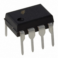
FSDL321 Fairchild Semiconductor, FSDL321 Datasheet

FSDL321
Specifications of FSDL321
FSDL321_NL
Related parts for FSDL321
FSDL321 Summary of contents
Page 1
... FSDH321, FSDL321 Green Mode Fairchild Power Switch (FPS Features • Internal Avalanche Rugged Sense FET • Consumes only 0.65W at 240VAC & 0.3W load with Advanced Burst-Mode Operation • Frequency Modulation for EMI Reduction • Precision Fixed Operating Frequency • Internal Start-up Circuit • ...
Page 2
... FSDH321, FSDL321 Internal Block Diagram + V - BURH V /V BURL BURH Vcc Vcc I I Vfb DELAY FB 3 2.5R Ipk 4 Soft Start V SD Vcc Vovp TSD 2 Vcc 2 8V/12V Vcc Freq. Modulation I BUR(pk) OSC Normal PWM Burst Vcc good R Q Figure 2. Functional Block Diagram of FSDx321 ...
Page 3
... The drain pins are designed to connect directly to the primary lead of the transformer and are capable of switching a maximum of 650V. Minimizing the length of the trace connecting these pins to the transformer will decrease leakage inductance. 8DIP 8LSOP Drain GND 1 8 Vcc 2 Drain 7 Vfb 6 Drain 3 Ipk 4 5 Vstr Figure 3. Pin Configuration (Top View) FSDH321, FSDL321 3 ...
Page 4
... FSDH321, FSDL321 Absolute Maximum Ratings (Ta=25°C, unless otherwise specified) Characteristic Drain Pin Voltage Vstr Pin Voltage Drain-Gate Voltage Gate-Source Voltage (1) Drain Current Pulsed Continuous Drain Current (Tc=25℃) Continuous Drain Current (Tc=100℃) Single Pulsed Avalanche Energy Supply Voltage Feedback Voltage Range ...
Page 5
... FB 0.7 0. FSDH321, FSDL321 Max. Unit 25 µA 200 Ω 110 KHz ±3.5 KHz 55 KHz ±2.0 KHz ± 1 0 0.80 ...
Page 6
... FSDH321, FSDL321 Comparison Between FSDM311 and FSDx321 Function Soft-Start 15ms External Current Limit not applicable Frequency Modulation not applicable Burst Mode Operation Built into controller Drain Creepage at 7.62mm Package 6 FSDM311 FSDx321 15ms Programmable of default current limit ±3.0KHz @100KHz ±1.5KHz @50KHz Built into controller 7 ...
Page 7
... T emp[ ℃ ] Frequency Modulation (∆F MOD 1.20 1.00 0.80 0.60 0.40 0.20 0.00 - emp[ ℃ ] Operating Supply Current (I OP 1.20 1.00 0.80 0.60 0.40 0.20 0.00 - emp[ ℃ ] Stop Threshold Voltage (V STOP FSDH321, FSDL321 100 150 ) vs. Ta 100 150 ) vs. Ta 100 150 ) vs ...
Page 8
... FSDH321, FSDL321 Typical Performance Characteristics 1.20 1.00 0.80 0.60 0.40 0.20 0.00 - emp[ ℃ ] Feedback Source Current (I 1.20 1.00 0.80 0.60 0.40 0.20 0.00 - emp[ ℃ ] Peak Current Limit (I 1.20 1.00 0.80 0.60 0.40 0.20 0.00 - emp[ ℃ ] Over Voltage Protection (V ...
Page 9
... Cfb from with 5uA current source. ) after the Sense FET is turned on. LEB (8V), the protection is reset and STOP (12V), the FPS resumes its normal START ). If V exceeds 3V, the feed increases until it reaches 6V, when the switching opera- FSDH321, FSDL321 DE- 9 ...
Page 10
... FSDH321, FSDL321 V FB Over Load Protection × (V(t )-V − µ DELAY I DELAY Figure 6. Over Load Protection (OLP) 4.2 Thermal Shutdown (TSD) : The Sense FET and the control IC are integrated, making it easier for the control IC to detect the temperature of the Sense FET. When the tem- perature exceeds approximately 145° ...
Page 11
... As can be seen in Figure 10, the frequency changes from 97KHz to 103KHz in 4ms for the FSDH321 (48.5KHz to 51.5KHz is driven FB for FSDL321). Frequency modulation allows the use of a cost effective inductor instead input mode choke to satisfy the requirements of world wide EMI limits. 103kHz 100kHz ...
Page 12
... FSDH321, FSDL321 Frequency (MHz) Figure 11. KA5-series FPS Full Range EMI scan(67KHz, no Frequency Modulation) with DVD Player SET Frequency (MHz) Figure 12. FSDX-series FPS Full Range EMI Scan (67KHz, with Frequency Modulation) with DVD Player SET 12 8. Adjusting Peak Current Limit : As shown in Figure 13, a combined 2.8kΩ ...
Page 13
... AN-4140: Transformer Design Consideration for Off-line Flyback Converters using Fairchild Power Switch ), F (FPS ) as shown in F AN-4141: Troubleshooting and Design Tips for Fairchild Power Switch (FPS AN-4147: Design Guidelines for RCD Snubber of Flyback AN-4148: Audible Noise Reduction Techniques for FPS Applications FSDH321, FSDL321 Flyback Applications ) 13 ...
Page 14
... FSDH321, FSDL321 Typical Application Circuit Application Output power PC Auxiliary Power Supply Features • High efficiency (>70% at full load, full input range) • Low standby mode power consumption (< 375V input and 0.5W load) • Low component count • Enhanced system reliability through various protection functions • ...
Page 15
... N M Vcc Winding Specification → tio → tio → tio → tio → tio Electrical Characteristics Core & Bobbin Core : EER1625 Bobbin : EER1625 EE1625 → ire φ × φ × φ × φ × φ × - - FSDH321, FSDL321 Vcc ...
Page 16
... FSDH321, FSDL321 6. Demo Circuit Part List Part Value Resistor R101 680K R102 100K R103 10 R104 10 R201 1K R202 330 R203 2K R204 2K Capacitor C101 10nF/630V C102 47uF/50V C103 10uF/50V C104 22nF/50V C201 1000uF/16V C202 100nF/50V C203 1uF/100V C204 470uF/16V C301 2.2nF/35V 16 Note Part ...
Page 17
... Package Dimensions 8DIP FSDH321, FSDL321 17 ...
Page 18
... FSDH321, FSDL321 Package Dimensions 18 (Continued) 8LSOP ...
Page 19
... Ordering Information Product Number Package FSDH321 8DIP FSDL321 8DIP FSDH321L 8LSOP FSDL321L 8LSOP Marking Code BV DSS DH321 650V DL321 650V DH321 650V DL321 650V FSDH321, FSDL321 f R OSC DS(ON) 100KHz 14Ω 50KHz 14Ω 100KHz 14Ω 50KHz 14Ω 19 ...
Page 20
... FSDH321, FSDL321 DISCLAIMER FAIRCHILD SEMICONDUCTOR RESERVES THE RIGHT TO MAKE CHANGES WITHOUT FURTHER NOTICE TO ANY PRODUCTS HEREIN TO IMPROVE RELIABILITY, FUNCTION OR DESIGN. FAIRCHILD DOES NOT ASSUME ANY LIABILITY ARISING OUT OF THE APPLICATION OR USE OF ANY PRODUCT OR CIRCUIT DESCRIBED HEREIN; NEITHER DOES IT CONVEY ANY LICENSE UNDER ITS PATENT RIGHTS, NOR THE RIGHTS OF OTHERS. ...


