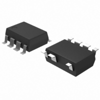
FSD200BM Fairchild Semiconductor, FSD200BM Datasheet - Page 13

FSD200BM
Manufacturer Part Number
FSD200BM
Description
IC SWIT PWM GREEN UVLO HV 7SOP
Manufacturer
Fairchild Semiconductor
Datasheet
1.FSD200BM.pdf
(18 pages)
Specifications of FSD200BM
Output Isolation
Isolated
Frequency Range
126 ~ 142kHz
Voltage - Input
6 ~ 10 V
Voltage - Output
670V
Power (watts)
7W
Operating Temperature
25°C ~ 100°C
Package / Case
8-SOP (7 Leads)
Power Switch Family
FSD200
Input Voltage
-0.3 to 10V
Power Switch On Resistance
28Ohm
Number Of Outputs
Single
Mounting
Surface Mount
Supply Current
600uA
Package Type
SOP
Operating Temperature (min)
-25C
Operating Temperature (max)
85C
Operating Temperature Classification
Commercial
Pin Count
7
Power Dissipation
1450W
Lead Free Status / RoHS Status
Lead free / RoHS Compliant
Other names
FSD200BM_NL
FSD200BM_NL
FSD200BM_NL
Available stocks
Company
Part Number
Manufacturer
Quantity
Price
Company:
Part Number:
FSD200BM/FSD200M
Manufacturer:
FAI
Quantity:
1 950
Company:
Part Number:
FSD200BMX
Manufacturer:
FSC
Quantity:
2 000
Company:
Part Number:
FSD200BMX
Manufacturer:
EUDYNA
Quantity:
100
Typical Application Circuit - 1
Features
• High efficiency (>67% at Universal Input)
• Low zero load power consumption (<100mW at 240Vac) with FSD210B
• Low component count
• Enhanced system reliability through various protection functions
• Internal soft-start (3ms)
• Frequency Modulation for low EMI
Key Design Notes
• The constant voltage (CV) mode control is implemented with resistors R8, R9, R10 and R11, shunt regulator U2, feedback
• The constant current (CC) mode control is designed with resistors R8, R9, R15, R16, R17 and R19, NPN transistor Q1 and
• The NTC(negative thermal coefficient) resistor is used to compensate the temperature characteristics of the transistor Q1.
• The zener diodes (ZD1, ZD2) are used to bypass the ESD or surge.
1. Schematic
Cellular Phone Charger
capacitor C9 and opto-coupler U3.
NTC TH1. When the voltage across current sensing resistors R15,R16 and R17 is 0.7V, the NPN transistor turns on and the
current through the opto coupler LED increases. This reduces the feedback voltage and duty ratio. Therefore, the output
voltage decreases and the output current is regulated.
AC
AC
Application
10R 1W
FUSE
For FSD21x
1N4007
1N4007
FSD210
D1
D3
U1
8
Vstr
1N4007
1N4007
D4
D2
C1
4.7uF 400V
Vcc
Vfb
L1 330uH
R1 4.7kΩ
Output power
100nF
5
4
C4
3.38W
ZD1
19V
H11A817B
C2
4.7uF 400V
33uF 50V
C5
ZD2
19V
47kΩ
47kΩ
R3
R4
UF4007
Universal input (85-265Vac)
D5
1N4148
D6
1nF
1kV
C3
4.7M 0.25W
Input voltage
39R
R4
R6
1.5nF-Y 250VAC
1
2
3
4
C6
4.7M 0.25W
T1
R7
7
8
2N2222
Q1
SB260
D7
4.7uF 50V
TH1 10K
C7
330uF
16V
510R
C10
R8
R19
510R
Output voltage (Max current)
56R
R9
U3
H11A817A
R13
300R
U2
TL431
C9 470nF
3.9uH
L3
2.2K
R10
5.2V (650mA)
R15 3R0
R16 3R0
R17 3R0
R12
2K
R14
150R
C8
330uF 16V
FSD210B, FSD200B
Vo
(5.2V, 0.65A)
13


