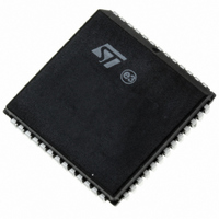
PSD813F1A-90JI STMicroelectronics, PSD813F1A-90JI Datasheet - Page 30

PSD813F1A-90JI
Manufacturer Part Number
PSD813F1A-90JI
Description
IC FLASH 1MBIT 90NS 52PLCC
Manufacturer
STMicroelectronics
Datasheet
1.PSD813F1A-90U.pdf
(111 pages)
Specifications of PSD813F1A-90JI
Format - Memory
FLASH
Memory Type
FLASH
Memory Size
1M (128K x 8)
Speed
90ns
Interface
Parallel
Voltage - Supply
4.5 V ~ 5.5 V
Operating Temperature
-40°C ~ 85°C
Package / Case
52-PLCC
Lead Free Status / RoHS Status
Contains lead / RoHS non-compliant
Other names
497-1976-5
Available stocks
Company
Part Number
Manufacturer
Quantity
Price
Company:
Part Number:
PSD813F1A-90JI
Manufacturer:
WSI
Quantity:
10
Company:
Part Number:
PSD813F1A-90JI
Manufacturer:
STMicroelectronics
Quantity:
10 000
PSD813F1A
FLASH AND EEPROM MEMORY SPECIFIC FEATURES
Flash Memory and EEPROM Sector Protect
Each Flash and EEPROM sector can be separate-
ly protected against Program and Erase functions.
Sector Protection provides additional data security
because it disables all program or erase opera-
tions. This mode can be activated through the
JTAG Port or a Device Programmer.
Sector protection can be selected for each sector
using the PSDsoft Configuration program. This will
automatically protect selected sectors when the
device is programmed through the JTAG Port or a
Device Programmer. Flash and EEPROM sectors
can be unprotected to allow updating of their con-
tents using the JTAG Port or a Device Program-
mer. The microcontroller can read (but cannot
change) the sector protection bits.
Table 10. Sector Protection/Security Bit Definition – Flash Protection Register
Note: 1. Bit Definitions:
Table 11. Sector Protection/Security Bit Definition – PSD/EE Protection Register
Note: 1. Bit Definitions:
SRAM
The SRAM is a 16 Kbit (2K x 8) memory. The
SRAM is enabled when RS0 the SRAM chip select
output from the DPLD is high. RS0 can contain up
30/111
Bit 7
Sec7_Prot
Bit 7
Security_Bit
Sec<i>_Prot 1 = Flash <i> is write protected.
Sec<i>_Prot 0 = Flash <i> is not write protected.
Sec<i>_Prot 1 = EEPROM Boot Sector <i> is write protected.
Sec<i>_Prot 0 = EEPROM Boot Sector <i> is not write protected.
Security_Bit 0 = Security Bit in device has not been set.
1 = Security Bit in device has been set.
Bit 6
Sec6_Prot
Bit 6
not used
Bit 5
Bit 5
Sec5_Prot
not used
Bit 4
Sec4_Prot
Bit 4
not used
Bit 3
Bit 3
Sec3_Prot
Sec3_Prot
Any attempt to program or erase a protected Flash
or EEPROM sector will be ignored by the device.
The Verify operation will result in a READ of the
protected data. This allows a guarantee of the re-
tention of the Protection status.
The sector protection status can be read by the
MCU through the Flash protection and PSD/EE
protection registers (CSIOP). See
Reset
The Reset instruction resets the internal memory
logic state machine in a few milliseconds. Reset is
an instruction of either one write operation or three
write operations (refer to
to two product terms, allowing flexible memory
mapping.
Bit 2
Sec2_Prot
Bit 2
Sec2_Prot
Bit 1
Sec1_Prot
Bit 1
Sec1_Prot
Table 8., page
Table 10.
Bit 0
Sec0_Prot
Bit 0
Sec0_Prot
20).


