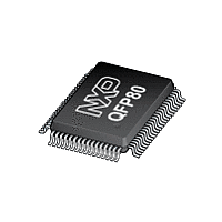
P8XC557E4 NXP Semiconductors, P8XC557E4 Datasheet - Page 46

P8XC557E4
Manufacturer Part Number
P8XC557E4
Description
The P80C557E4/P83C557E4/P89C557E4 (hereafter generically referred to as P8xC557E4) single-chip 8-bit microcontroller is manufactured in an advanced CMOS process and is a derivative of the 80C51 microcontroller family
Manufacturer
NXP Semiconductors
Datasheet
1.P8XC557E4.pdf
(72 pages)
- Current page: 46 of 72
- Download datasheet (375Kb)
Philips Semiconductors
6.14 Reset Circuitry
The reset input pin RSTIN is connected to a Schmitt trigger for noise
reduction (see Figure 46). Is the HF-oscillator selected a Reset is
accomplished by holding the RSTIN pin HIGH for at least 2 machine
cycles (24 system clock periods). Is the PLL-oscillator selected the
RSTIN-pulse must have a width of 1 s at least, independent of the
32 kHz-oscillator is running or not (see PLL description). The CPU
responds by executing an internal reset. The RSTOUT pin
represents the signal resetting the CPU and can be used to reset
peripheral devices.
The RSTOUT level also could be high due to a Watchdog timer
overflow.
The length of the output pulse from T3 is 3 machine cycles. A pulse
of such short duration is necessary in order to recover from a
processor or system fault as fast as possible.
During Reset, ALE and PSEN output a HIGH level. In order to
perform a correct reset, this level must not be affected by external
elements.
A Reset leaves the internal registers as shown in Table 5.
The internal RAM is not affected by Reset. At power-on, the RAM
content is indeterminate.
1999 Mar 02
RSTIN
SELXTAL1
Single-chip 8-bit microcontroller
On-chip
resistor
Figure 46. On-chip Reset Configuration
R
RST
Schmitt
Trigger
PLL
OSC
MUX
Overflow
timer T3
Internal
Reset
RSTOUT
46
P83C557E4/P80C557E4/P89C557E4
6.15 Power-on Reset
An automatic Reset can be obtained by switching on V
RSTIN pin is connected to V
Figure 47.
Is the HF oscillator selected the V
ms and the capacitor should be at least 2.2 F. The decrease of the
RSTIN pin voltage depends on the capacitor and the internal resistor
R
minimum the HF-oscillator start-up time plus 2 machine cycles. Is
the PLL-oscillator selected a 0.1 F capacitor is sufficient to obtain
an automatic reset.
RST
. That voltage must remain above the lower threshold for at
Capacitor for
HF-Osc.:
PLL-Osc.: 0.1 F
2.2 F
Figure 47. Power-on Reset
V
DD
DD
via a capacitor, as shown in
DD
rise time must not exceed 10
RST
8xC557E4
R
RST
Product specification
V
DD
DD
, if the
Related parts for P8XC557E4
Image
Part Number
Description
Manufacturer
Datasheet
Request
R
Part Number:
Description:
NXP Semiconductors designed the LPC2420/2460 microcontroller around a 16-bit/32-bitARM7TDMI-S CPU core with real-time debug interfaces that include both JTAG andembedded trace
Manufacturer:
NXP Semiconductors
Datasheet:

Part Number:
Description:
NXP Semiconductors designed the LPC2458 microcontroller around a 16-bit/32-bitARM7TDMI-S CPU core with real-time debug interfaces that include both JTAG andembedded trace
Manufacturer:
NXP Semiconductors
Datasheet:
Part Number:
Description:
NXP Semiconductors designed the LPC2468 microcontroller around a 16-bit/32-bitARM7TDMI-S CPU core with real-time debug interfaces that include both JTAG andembedded trace
Manufacturer:
NXP Semiconductors
Datasheet:
Part Number:
Description:
NXP Semiconductors designed the LPC2470 microcontroller, powered by theARM7TDMI-S core, to be a highly integrated microcontroller for a wide range ofapplications that require advanced communications and high quality graphic displays
Manufacturer:
NXP Semiconductors
Datasheet:
Part Number:
Description:
NXP Semiconductors designed the LPC2478 microcontroller, powered by theARM7TDMI-S core, to be a highly integrated microcontroller for a wide range ofapplications that require advanced communications and high quality graphic displays
Manufacturer:
NXP Semiconductors
Datasheet:
Part Number:
Description:
The Philips Semiconductors XA (eXtended Architecture) family of 16-bit single-chip microcontrollers is powerful enough to easily handle the requirements of high performance embedded applications, yet inexpensive enough to compete in the market for hi
Manufacturer:
NXP Semiconductors
Datasheet:
Part Number:
Description:
The XA-S3 device is a member of Philips Semiconductors? XA(eXtended Architecture) family of high performance 16-bitsingle-chip microcontrollers
Manufacturer:
NXP Semiconductors
Datasheet:

Part Number:
Description:
The NXP BlueStreak LH75401/LH75411 family consists of two low-cost 16/32-bit System-on-Chip (SoC) devices
Manufacturer:
NXP Semiconductors
Datasheet:

Part Number:
Description:
The NXP LPC3130/3131 combine an 180 MHz ARM926EJ-S CPU core, high-speed USB2
Manufacturer:
NXP Semiconductors
Datasheet:

Part Number:
Description:
The NXP LPC3141 combine a 270 MHz ARM926EJ-S CPU core, High-speed USB 2
Manufacturer:
NXP Semiconductors

Part Number:
Description:
The NXP LPC3143 combine a 270 MHz ARM926EJ-S CPU core, High-speed USB 2
Manufacturer:
NXP Semiconductors

Part Number:
Description:
The NXP LPC3152 combines an 180 MHz ARM926EJ-S CPU core, High-speed USB 2
Manufacturer:
NXP Semiconductors

Part Number:
Description:
The NXP LPC3154 combines an 180 MHz ARM926EJ-S CPU core, High-speed USB 2
Manufacturer:
NXP Semiconductors

Part Number:
Description:
Standard level N-channel enhancement mode Field-Effect Transistor (FET) in a plastic package using NXP High-Performance Automotive (HPA) TrenchMOS technology
Manufacturer:
NXP Semiconductors
Datasheet:


