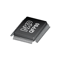
P8XC557E4 NXP Semiconductors, P8XC557E4 Datasheet - Page 42

P8XC557E4
Manufacturer Part Number
P8XC557E4
Description
The P80C557E4/P83C557E4/P89C557E4 (hereafter generically referred to as P8xC557E4) single-chip 8-bit microcontroller is manufactured in an advanced CMOS process and is a derivative of the 80C51 microcontroller family
Manufacturer
NXP Semiconductors
Datasheet
1.P8XC557E4.pdf
(72 pages)
Philips Semiconductors
6.11.1 Power Control Register
The modes Idle and Power-down are activated by software via the
Special Function Register PCON. Its hardware address is 87H.
PCON is not bit addressable. The reset value of PCON is
(00000000).
6.11.2 Idle Mode
The instruction that sets PCON.0 is the last instruction executed in
the normal operating mode before Idle Mode is activated. Once in
the Idle Mode, the CPU status is preserved in its entirety: the Stack
Pointer, Program Counter, Program Status Word, Accumulator, RAM
and all other registers maintain their data during Idle Mode. The
status of external pins during Idle Mode is shown in Table 40.
There are three ways to terminate the Idle Mode:
Activation of any enabled interrupt X0, T0, X1, SEC, T1, S0 or S1
will cause PCON.0 to be cleared by hardware terminating Idle Mode
but only, if there is no interrupt in service with the same or higher
priority. The interrupt is serviced, and following return from interrupt
instruction RETI, the next instruction to be executed will be the one
which follows the instruction that wrote a logic 1 to PCON.0.
1999 Mar 02
XTAL1,2
32 kHz oscillator stopped
INT0
INT1
Single-chip 8-bit microcontroller
oscillator stopped
Internal timing stopped
running
Power-down Mode
XTAL4
XTAL1
Seconds timer
Figure 40. Idle and Power Down Hardware for Clock Generation
32 kHz
16 MHz
3.5 to
oscillator start_up
Osc
Osc
PLL
> 560 ms
> 10 ms
Figure 41. Wake-up by interrupt
XTAL3
XTAL2
set External Interrupt latch
SELXTAL1
> 10 ms
PD
42
P83C557E4/P80C557E4/P89C557E4
The flag bits GF0 and GF1 may be used to determine whether the
interrupt was received during normal execution or during Idle Mode.
For example, the instruction that writes to PCON.0 can also set or
clear one or both flag bits. When Idle Mode is terminated by an
interrupt, the service routine can examine the status of the flag bits.
The second way of terminating the Idle Mode is with an external
hardware reset. Since the oscillator is still running, the hardware
reset is required to be active for two machine cycles (24 HF
oscillator periods) to complete the reset operation if the HF oscillator
is selected.
When the PLL oscillator is selected a hardware reset of > 1 sec
(but no longer than 10 ms) is required and the microcontroller will
typically restart within 63 msec after the reset has finished.
The third way of terminating the Idle Mode is by internal watchdog
reset. The microcontroller restarts after 3 machine cycles in all
cases.
f
CLK
C1
interrupts are polled
Clock
Gen.
INT0 : 2 cycles
INT1 : 1 cycle
Idle Mode
IDL
C1
Interrupts,
Serial
Ports,
T0, T1, T3
CPU
T2
ADC
PWM
C1
Interrupt routine
LCALL
Product specification
C2


