LM49101TM/NOPB National Semiconductor, LM49101TM/NOPB Datasheet - Page 23
LM49101TM/NOPB
Manufacturer Part Number
LM49101TM/NOPB
Description
IC AUDIO SUBSYSTM 1.3W AB 25USMD
Manufacturer
National Semiconductor
Series
Boomer®, PowerWise®r
Type
Class ABr
Datasheet
1.LM49101TMNOPB.pdf
(30 pages)
Specifications of LM49101TM/NOPB
Output Type
1-Channel (Mono) with Stereo Headphones
Max Output Power X Channels @ Load
1.3W x 1 @ 8 Ohm; 45mW x 2 @ 32 Ohm
Voltage - Supply
2.7 V ~ 5.5 V
Features
Depop, Differential Inputs, I²C, Shutdown, Thermal Protection, Volume Control
Mounting Type
Surface Mount
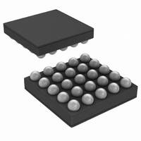
Package / Case
25-MicroSMD
Operational Class
Class-AB
Audio Amplifier Output Configuration
1-Channel Mono/2-Channel Stereo
Audio Amplifier Function
Headphone/Speaker
Single Supply Voltage (typ)
Not RequiredV
Dual Supply Voltage (typ)
3/5V
Power Supply Requirement
Triple
Rail/rail I/o Type
No
Power Supply Rejection Ratio
90dB
Single Supply Voltage (min)
Not RequiredV
Single Supply Voltage (max)
Not RequiredV
Dual Supply Voltage (min)
1.7/1.8/2.7V
Dual Supply Voltage (max)
2.9/5.5V
Operating Temp Range
-40C to 85C
Operating Temperature Classification
Industrial
Mounting
Surface Mount
Pin Count
25
Package Type
uSMD
Lead Free Status / RoHS Status
Lead free / RoHS Compliant
Other names
LM49101TMTR


DIFFERENTIAL AMPLIFIER EXPLANATION
The LM49101 features a differential input stage, which offers
improved noise rejection compared to a single-ended input
amplifier. Because a differential input amplifier amplifies the
difference between the two input signals, any component
common to both signals is cancelled. An additional benefit of
the differential input structure is the possible elimination of the
DC input blocking capacitors. Since the DC component is
common to both inputs, and thus cancelled by the amplifier,
the LM49101 can be used without input coupling capacitors
when configured with a differential input signal.
BRIDGE CONFIGURATION EXPLAINED
By driving the load differentially through the MONO outputs,
an amplifier configuration commonly referred to as “bridged
mode” is established. Bridged mode operation is different
from the classical single-ended amplifier configuration where
one side of the load is connected to ground.
A bridge amplifier design has a few distinct advantages over
the single-ended configuration, as it provides differential drive
to the load, thus doubling output swing for a specified supply
voltage. Four times the output power is possible as compared
to a single-ended amplifier under the same conditions. This
increase in attainable output power assumes that the ampli-
fier is not current limited or clipped.
A bridge configuration, such as the one used in LM49101,
also creates a second advantage over single-ended ampli-
fiers. Since the differential outputs are biased at half-supply,
no net DC voltage exists across the load. This eliminates the
need for an output coupling capacitor which is required in a
single supply, single-ended amplifier configuration. Without
an output coupling capacitor, the half-supply bias across the
load would result in both increased internal IC power dissipa-
tion and also possible loudspeaker damage.
POWER DISSIPATION
Power dissipation is a major concern when designing a suc-
cessful amplifier, whether the amplifier is bridged or single-
ended. A direct consequence of the increased power
delivered to the load by a bridge amplifier is an increase in
internal power dissipation. The power dissipation of the
LM49101 varies with the mode selected. The maximum pow-
er dissipation occurs in modes where all inputs and outputs
are active (Modes 6, 7, 8, 9, 10, 11, 13, 14, 15). The power
dissipation is dominated by the Class AB amplifier. The max-
imum power dissipation for a given application can be derived
from the power dissipation graphs or from Equation 1.
It is critical that the maximum junction temperature (T
150°C is not exceeded. T
power derating curves by using P
area. By adding additional copper foil, the thermal resistance
of the application can be reduced from the free air value, re-
sulting in higher P
to any of the leads connected to the LM49101. It is especially
effective when connected to V
Refer to the application information on the LM49101 refer-
ence design board for an example of good heat sinking. If
T
made. These changes can include reduced supply voltage,
higher load impedance, or reduced ambient temperature. In-
ternal power dissipation is a function of output power. Refer
to the Typical Performance Characteristics curves for
JMAX
still exceeds 150°C, then additional changes must be
P
DMAX
DMAX
= 4*(V
. Additional copper foil can be added
JMAX
DD
)
DD
2
/(2
can be determined from the
, GND, and the output pins.
DMAX
π
2
R
L
and the PC board foil
)
JMAX
) of
(1)
23
power dissipation information for different output powers and
output loading.
POWER SUPPLY BYPASSING
As with any amplifier, proper supply bypassing is critical for
low noise performance and high power supply rejection. The
capacitor location on both the bypass and power supply pins
should be as close to the device as possible. Typical appli-
cations employ a 5V regulator with 10µF tantalum or elec-
trolytic capacitor and a ceramic bypass capacitor which aid in
supply stability. This does not eliminate the need for bypass-
ing the supply nodes of the LM49101. The selection of a
bypass capacitor, especially C
requirements, click and pop performance, system cost, and
size constraints.
GROUND REFERENCED HEADPHONE AMPLIFIER
The LM49101 features a low noise inverting charge pump that
generates an internal negative supply voltage. This allows the
headphone outputs to be biased about GND instead of a
nominal DC voltage, like traditional headphone amplifiers.
Because there is no DC component, the large DC blocking
capacitors (typically 220μF) are not necessary. The coupling
capacitors are replaced by two small ceramic charge pump
capacitors, saving board space and cost. Eliminating the out-
put coupling capacitors also improves low frequency re-
sponse. In traditional headphone amplifiers, the headphone
impedance and the output capacitor from a high-pass filter
that not only blocks the DC component of the output, but also
attenuates low frequencies, impacting the bass response.
Because the LM49101 does not require the output coupling
capacitors, the low frequency response of the device is not
degraded by external components. In addition to eliminating
the output coupling capacitors, the ground referenced output
nearly doubles the available dynamic range of the LM49101
headphone amplifiers when compared to a traditional head-
phone amplifier operating from the same supply voltage.
HEADPHONE & CHARGE PUMP SUPPLY VOLTAGE
(V
The headphone outputs are centered at ground by using dual
supply voltages for the headphone amplifier. The positive
power supply is set by the voltage on the V
negative supply is created with an internal charge pump. The
negative supply voltage is equal in magnitude but opposite in
voltage to the voltage on the V
INPUT CAPACITOR SELECTION
Input capacitors may be required for some applications, or
when the audio source is single-ended. Input capacitors block
the DC component of the audio signal, eliminating any conflict
between the DC component of the audio source and the bias
voltage of the LM49101. The input capacitors create a high-
pass filter with the input resistors R
high-pass filter is found using Equation (2) below.
Where the value of R
tics Table as Z
When the LM49101 is using a single-ended source, power
supply noise on the ground is seen as an input signal. Setting
the high-pass filter point above the power supply noise fre-
quencies, 217Hz in a GSM phone, for example, filters out the
noise such that it is not amplified and heard on the output.
DD
HP & V
DD
CP)
IN
f = 1 / 2
.
IN
π
is given in the Electrical Characteris-
R
IN
C
IN
DD
B
, is dependent upon PSRR
CP pin.
(Hz)
IN
. The -3dB point of the
DD
HP pin while the
www.national.com
(2)
Related parts for LM49101TM/NOPB
Image
Part Number
Description
Manufacturer
Datasheet
Request
R

Part Number:
Description:
National Semiconductor [8-Bit D/A Converter]
Manufacturer:
National Semiconductor
Datasheet:
Part Number:
Description:
National Semiconductor [Media Coprocessor]
Manufacturer:
National Semiconductor
Datasheet:
Part Number:
Description:
Digitally Controlled Tone and Volume Circuit with Stereo Audio Power Amplifier, Microphone Preamp Stage and National 3D Sound
Manufacturer:
National Semiconductor
Datasheet:
Part Number:
Description:
Digitally Controlled Tone and Volume Circuit with Stereo Audio Power Amplifier, Microphone Preamp Stage and National 3D Sound
Manufacturer:
National Semiconductor
Datasheet:
Part Number:
Description:
AC97 Rev 2 Codec with Sample Rate Conversion and National 3D Sound
Manufacturer:
National Semiconductor
Part Number:
Description:
Manufacturer:
National Semiconductor
Datasheet:
Part Number:
Description:
Manufacturer:
National Semiconductor
Datasheet:
Part Number:
Description:
General Purpose, Low Voltage, Low Power, Rail-to-Rail Output Operational Amplifiers
Manufacturer:
National Semiconductor
Datasheet:
Part Number:
Description:
8-bit 20 MSPS flash A/D converter.
Manufacturer:
National Semiconductor
Datasheet:
Part Number:
Description:
Low Noise Quad Operational Amplifier
Manufacturer:
National Semiconductor
Datasheet:
Part Number:
Description:
Quad Differential Line Receivers
Manufacturer:
National Semiconductor
Datasheet:
Part Number:
Description:
Quad High Speed Trapezoidal? Bus Transceiver
Manufacturer:
National Semiconductor
Datasheet:
Part Number:
Description:
Dual Line Receiver
Manufacturer:
National Semiconductor
Datasheet:
Part Number:
Description:
TTL to 10k ECL Level Translator with Latch
Manufacturer:
National Semiconductor
Datasheet: