LM49101TM/NOPB National Semiconductor, LM49101TM/NOPB Datasheet - Page 22
LM49101TM/NOPB
Manufacturer Part Number
LM49101TM/NOPB
Description
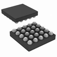
IC AUDIO SUBSYSTM 1.3W AB 25USMD
Manufacturer
National Semiconductor
Series
Boomer®, PowerWise®r
Type
Class ABr
Datasheet
1.LM49101TMNOPB.pdf
(30 pages)
Specifications of LM49101TM/NOPB
Output Type
1-Channel (Mono) with Stereo Headphones
Max Output Power X Channels @ Load
1.3W x 1 @ 8 Ohm; 45mW x 2 @ 32 Ohm
Voltage - Supply
2.7 V ~ 5.5 V
Features
Depop, Differential Inputs, I²C, Shutdown, Thermal Protection, Volume Control
Mounting Type
Surface Mount
Package / Case
25-MicroSMD
Operational Class
Class-AB
Audio Amplifier Output Configuration
1-Channel Mono/2-Channel Stereo
Audio Amplifier Function
Headphone/Speaker
Single Supply Voltage (typ)
Not RequiredV
Dual Supply Voltage (typ)
3/5V
Power Supply Requirement
Triple
Rail/rail I/o Type
No
Power Supply Rejection Ratio
90dB
Single Supply Voltage (min)
Not RequiredV
Single Supply Voltage (max)
Not RequiredV
Dual Supply Voltage (min)
1.7/1.8/2.7V
Dual Supply Voltage (max)
2.9/5.5V
Operating Temp Range
-40C to 85C
Operating Temperature Classification
Industrial
Mounting
Surface Mount
Pin Count
25
Package Type
uSMD
Lead Free Status / RoHS Status
Lead free / RoHS Compliant
Other names
LM49101TMTR


www.national.com
HW RESET FUNCTION
The LM49101 can be globally reset without using the I
trols. When the HW RESET pin is set to a logic low the
LM49101 will enter into shutdown, the mode control bits of the
Output Mode Control register, volume control registers and
Power_On bits will be set to the default value of zero. The
other bits will retain their values. The LM49101 cannot be ac-
tivated until the HW RESET pin is set to a logic high voltage.
When the HW RESET is set to a logic high then the I
trols can activate and set the register control bits.
GAMP_SD BIT
The GAMP_SD bit allows for reduced power consumption.
When set to '1' the gain amplifiers on unused inputs will be
shutdown saving approximately 0.4mA per input in shutdown.
For example, in Mode 1 only the mono inputs are in use. Set-
ting GAMP_SD to '1' will shut down the gain amplifiers for the
left and right inputs reducing current draw from the V
supply by approximately 0.8mA. The GAMP_SD bit does not
need to be set each time when changing modes as the
LM49101 will automatically activate and deactivate the need-
ed inputs based on the mode selected.
When operating with GAMP_SD set to '1', a transient may be
observed on the outputs when changing modes. During pow-
er up, the LM49101 uses a start up sequence to eliminate any
pops and clicks on the outputs. The volume control circuitry
is powered up first followed by the other internal circuitry with
the output amplifiers being powered up last. If a mode change
requires a gain amplifier to turn on then a potential transient
may be created that is amplified on the already active outputs.
To eliminate unwanted noise on the outputs the Power_On
bit should be used to turn off the LM49101 before changing
modes, perform a mode change, then turn the LM49101 back
on. This procedure will cause the LM49101 to follow the start
up sequence.
LS (EP_MODE) BIT
The LS (EP_Mode) bit selects the amount of bias current in
the loudspeaker amplifier. Setting the LS (EP_Mode) bit to a
'1' will reduce the amount of current from the V
by approximately 0.5mA. The THD performance of the loud-
speaker amplifier will be reduced as a result of lower bias
current. See the performance graphs in the Typical Perfor-
mance Characteristics section above.
TURN_ON_TIME BIT
The Turn_On_Time bit determines the delay time from the
Power_On bit set to '1' and the internal circuits ready. For
input capacitor values up to 0.47μF the Turn_On_Time bit can
be set to fast mode by setting the bit to a '1'. When the input
capacitor values are larger than 0.47μF then the
Turn_On_Time bit should be set to '0' for normal turn-on time
and higher delay. This allows sufficient time to charge the in-
put capacitors to the ½ V
POWER_ON BIT
The Power_On bit is the master control bit to activate or de-
activate the LM49101. All registers can be loaded indepen-
dent of the Power_On bit setting as long as the IC is powered
correctly. Cycling the Power_On bit does not change the val-
ues of any registers nor return all bits to the default power on
value of zero. The Power_On bit only determines whether the
IC is on or off.
EP BYPASS BIT
The EP Bypass bit is used to set the LM49101 to earpiece
mode. When this bit is set the analog switch is activated and
DD
LS bias voltage.
DD
LS supply
2
2
C con-
C con-
DD
LS
22
the rest of the IC blocks except for the I
shutdown for minimal current consumption.
HPR_SD BIT
The HPR_SD bit will deactivate the right headphone output
amplifier. This bit is provided to reduce power consumption
when only one headphone output is needed.
MODE_CONTROL BITS
The LM49101 includes a comprehensive mixer multiplexer
controlled through the I
lows any input combination to appear on any output of
LM49101. Multiple input paths can be selected simultane-
ously. Under these conditions, the selected inputs are mixed
together and output on the selected channel. Table 4 shows
how the input signals are mixed together for each possible
input selection.
INPUT MUTE BIT
The Input Mute bit will mute all inputs except the Bypass in-
puts when set to a '1'. This allows complete and quick mute
of the Mono, Left, and Right inputs without changing the Vol-
ume Control registers or HP_Gain bits. The volume and
HP_Gain bits retain their values when the Input Mute is en-
abled or disabled.
The Input Mute bit can be used to mute all the inputs when
other chips in a system, such as the baseband IC, create
transients causing unwanted noise on the outputs of the
LM49101. This added feature eliminates the need for power
cycling the LM49101.
LS_GAIN BIT
The loudspeaker amplifier can have an additional gain of 0dB
or 6dB by using the LS_Gain bit. The Mono input has 6dB of
attenuation before the volume control (see Figure 1) while the
Left and Right inputs do not. The LS_Gain bit is used to ac-
count for the different attenuation levels for each input and to
achieve maximum output power. To obtain maximum output
power on the loudspeaker outputs, the LS_Gain bit should be
se to '1' for Modes 1, 5, 9, 13.
HP_GAIN BITS
The headphone outputs have an additional, single volume
control set by the three HP_Gain bits in the Output Gain Con-
trol register. The HP_Gain volume setting controls the output
level for both the left and the right headphone outputs.
VOLUME CONTROL BITS
The LM49101 has three independent 32-step volume con-
trols, one for each of the inputs. The five bits of the Volume
Control registers sets the volume for the specified input chan-
nel.
SHUTDOWN FUNCTION
The LM49101 features the following shutdown controls.
Bit D4 (GAMP_SD) of the GENERAL CONTROL register
controls the gain amplifiers. When GAMP_SD = 1, it disables
the gain amplifiers that are not in use. For example, in Modes
1, 4 and 5, the Mono inputs are in use, so the Left and Right
input gain amplifiers are disabled, causing the I
imized.
Bit D0 (Power_On) of the GENERAL CONTROL register is
the global shutdown control for the entire device. Set
Power_On = 0 for normal operation. Power_On = 1 overrides
any other shutdown control bit.
2
C interface. The mixer/multiplexer al-
2
C circuitry will go into
DD
to be min-
Related parts for LM49101TM/NOPB
Image
Part Number
Description
Manufacturer
Datasheet
Request
R

Part Number:
Description:
National Semiconductor [8-Bit D/A Converter]
Manufacturer:
National Semiconductor
Datasheet:
Part Number:
Description:
National Semiconductor [Media Coprocessor]
Manufacturer:
National Semiconductor
Datasheet:
Part Number:
Description:
Digitally Controlled Tone and Volume Circuit with Stereo Audio Power Amplifier, Microphone Preamp Stage and National 3D Sound
Manufacturer:
National Semiconductor
Datasheet:
Part Number:
Description:
Digitally Controlled Tone and Volume Circuit with Stereo Audio Power Amplifier, Microphone Preamp Stage and National 3D Sound
Manufacturer:
National Semiconductor
Datasheet:
Part Number:
Description:
AC97 Rev 2 Codec with Sample Rate Conversion and National 3D Sound
Manufacturer:
National Semiconductor
Part Number:
Description:
Manufacturer:
National Semiconductor
Datasheet:
Part Number:
Description:
Manufacturer:
National Semiconductor
Datasheet:
Part Number:
Description:
General Purpose, Low Voltage, Low Power, Rail-to-Rail Output Operational Amplifiers
Manufacturer:
National Semiconductor
Datasheet:
Part Number:
Description:
8-bit 20 MSPS flash A/D converter.
Manufacturer:
National Semiconductor
Datasheet:
Part Number:
Description:
Low Noise Quad Operational Amplifier
Manufacturer:
National Semiconductor
Datasheet:
Part Number:
Description:
Quad Differential Line Receivers
Manufacturer:
National Semiconductor
Datasheet:
Part Number:
Description:
Quad High Speed Trapezoidal? Bus Transceiver
Manufacturer:
National Semiconductor
Datasheet:
Part Number:
Description:
Dual Line Receiver
Manufacturer:
National Semiconductor
Datasheet:
Part Number:
Description:
TTL to 10k ECL Level Translator with Latch
Manufacturer:
National Semiconductor
Datasheet: