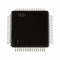
SC16C554IB64,151 NXP Semiconductors, SC16C554IB64,151 Datasheet - Page 53

SC16C554IB64,151
Manufacturer Part Number
SC16C554IB64,151
Description
IC UART QUAD SOT314-2
Manufacturer
NXP Semiconductors
Specifications of SC16C554IB64,151
Number Of Channels
4, QUART
Fifo's
16 Byte
Voltage - Supply
2.5V, 3.3V, 5V
With Auto Flow Control
Yes
With Irda Encoder/decoder
Yes
With False Start Bit Detection
Yes
With Modem Control
Yes
With Cmos
Yes
Mounting Type
Surface Mount
Package / Case
64-LQFP
Transmit Fifo
16Byte
Receive Fifo
16Byte
Transmitter And Receiver Fifo Counter
Yes
Data Rate
5Mbps
Package Type
LQFP
Operating Supply Voltage (max)
5.5V
Operating Supply Voltage (min)
4.5V
Mounting
Surface Mount
Operating Temperature (min)
-40C
Operating Temperature (max)
85C
Operating Temperature Classification
Industrial
Lead Free Status / RoHS Status
Lead free / RoHS Compliant
Other names
935270074151
SC16C554IB64-S
SC16C554IB64-S
SC16C554IB64-S
SC16C554IB64-S
Philips Semiconductors
13. Revision history
Table 29:
9397 750 13132
Product data
Rev Date
05
04
03
02
01
20040510
20030619
20030415
20030313
20020910
Revision history
CPCN
-
-
-
-
-
Description
Product data (9397 750 13132). Supersedes data of 19 June 2003 (9397 750 11616).
Modifications:
Product data (9397 750 11616); ECN 853-2376 30028 of 16 June 2003.
Product data (9397 750 11375); ECN 853-2376 29797 of 11 April 2003.
Product data (9397 750 11002); ECN 853-2376 29627 of 10 March 2003.
Product data; (9397 750 09213); ECN 853-2376 28891 of 10 September 2002.
•
•
•
•
•
•
Figure 6 “LQFP80 pin
from “D6” to “INTD”.
Table 2 “Pin description”
Section 6.4 “Internal
registers...” to “... provides 17 internal registers...”
Section 6.13 “Loop-back mode”
Table 9 “Interrupt Enable Register bits
Table 21 “Enhanced Feature Register bits
bit 4, EFR[4], modified.
– INTSEL description, last sentence: change from “The ST16C654IB64 ...” to “The
– RESET (RESET) description, last sentence: change from “... this pin functions similarly,
– First paragraph:
SC16C654IB64 ...”
bus as an inverted reset interface signal ...” to “... this pin functions similarly, but as an
inverted reset interface signal ...”
– change from “MCR signals DTR and RTS (bits 0-1) are used to control the modem
– Change from “...are connected internally to DTR, RTS, OP1 and OP2.” to “...are
–
CTS and DSR inputs, respectively.” to “MCR signals DTR and RTS (bits 0-1) are used
to control the modem DSR and CTS inputs, respectively.”
connected internally to RTS, DTR, OP2 and OP1.”
Figure 8
Quad UART with 16-byte FIFO and infrared (IrDA) encoder/decoder
and
Figure 9
Rev. 05 — 10 May 2004
registers”, first sentence: change from “... provides 15 internal
configuration.”: change pin 49 from “CSC” to “n.c.”; change pin 74
modified: signals to/from Modem Control Logic block corrected.
description”: description of bit 2, IER[2], modified.
description”: description of bit 6, EFR[6], and of
SC16C554/554D
© Koninklijke Philips Electronics N.V. 2004. All rights reserved.
53 of 55


