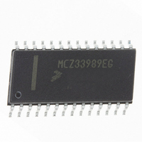
MCZ33989EG Freescale Semiconductor, MCZ33989EG Datasheet - Page 8

MCZ33989EG
Manufacturer Part Number
MCZ33989EG
Description
IC SYSTEM BASIS CHIP CAN 28-SOIC
Manufacturer
Freescale Semiconductor
Datasheet
1.MC33989DWR2.pdf
(66 pages)
Specifications of MCZ33989EG
Applications
*
Interface
*
Voltage - Supply
*
Package / Case
28-SOIC (7.5mm Width)
Mounting Type
Surface Mount
Lead Free Status / RoHS Status
Lead free / RoHS Compliant
Available stocks
Company
Part Number
Manufacturer
Quantity
Price
Part Number:
MCZ33989EG
Manufacturer:
FREESCALE
Quantity:
20 000
Company:
Part Number:
MCZ33989EGR2
Manufacturer:
EXAR
Quantity:
6 247
Table 3. Static Electrical Characteristics (continued)
values noted reflect the approximate parameter means at T
8
33989
ELECTRICAL CHARACTERISTICS
STATIC ELECTRICAL CHARACTERISTICS
POWER OUTPUT (VDD1) IN STOP MODE
TRACKING VOLTAGE REGULATOR (V2)
LOGIC OUTPUT PIN (MISO)
Notes
VDD1 Output Voltage
VDD1 Output Voltage
I
I
Reset Threshold
Reset Threshold
Line Regulation (C at V
Load Regulation (C at V
Max Decoupling Capacitor at VDD1 Pin, in Stop Mode
V2 Output Voltage (C at V2 = 10 µF Tantal)
I2 Output Current (for information only)
V2 Control Drive Current Capability
V2LOW Flag Threshold
Low Level Output Voltage
High Level Output Voltage
Tri-Stated MISO Leakage Current
DD1
DD1
16.
17.
18.
19.
20.
Characteristics noted under conditions 5.5 V ≤ V
I
I
5.5 V < V
1 mA < I
I2 from 2.0 to 200 mA, 5.5 V < V
Depending Upon External Ballast Transistor
Worst Case at T
I
I
0 V < V
DD1
DD1
OUT
OUT
Stop Output Current to Wake-up SBC
Over Current to Wake-up Deglitcher Time
If stop mode is used, the capacitor connected at VDD pin should not exceed the maximum specified by the “V
If capacitor value is exceeded, upon entering stop mode, VDD output current may exceed the I
stop mode.
Guaranteed by design; however, it is not production tested.
Guaranteed by design.
V2 specification with external capacitor
- Stability requirement: C > 42 µF and ESR < 1.3 Ω (Tantalum capacitor), external resistor between base and emitter required
- Measurement conditions: Ballast transistor MJD32C, C = 10 µF Tantalum, 2.2 k resistor between base and emitter of ballast transistor
Push/Pull structure with tri-state condition CS high.
< = 2.0 mA
< = 10 mA
= 1.5 mA
= 250 µA
MISO
DD
SUP
< 10 mA
< V
< 27 V, I
J
DD
= 125°C
DD1
DD1
DD
= 47 µF Tantal)
Characteristic
= 47 µF Tantal)
= 2.0 mA
(20)
SUP
< 27 V
(19)
(16)
(17)
(18)
SUP
≤ 18 V, - 40°C ≤ T
A
= 25°C under nominal conditions unless otherwise noted.
RST
RST
V
V
I
V
I
Symbol
DD1DGLT
DD1SWU
12
DDSTOP2
V2L
DDSTOP
DDst-cap
LR
LD
V
V
I
V2
A
CTRL
I2
HZ
STOP1
STOP2
OH
OL
S
S
TH
≤ 125°C, GND = 0 V unless otherwise noted. Typical
V
DD1-0.9
4.75
4.75
0.99
3.75
Min
200
-2.0
4.5
4.1
0.0
0.0
10
40
—
—
—
Analog Integrated Circuit Device Data
DDSWU
5.00
5.00
Typ
4.6
4.2
5.0
1.0
4.0
and prevent the device to stay in
17
55
15
—
—
—
—
—
—
Freescale Semiconductor
DDst-cap
V
Max
5.25
5.25
1.01
4.25
200
4.7
4.3
1.0
2.0
25
75
25
75
10
—
DD1
” parameter.
V
Unit
mA
mV
mV
mA
mA
µF
µA
µs
DD1
V
V
V
V
V
V
V


