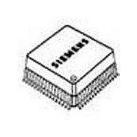
PEF82912FV14XP Lantiq, PEF82912FV14XP Datasheet - Page 27

PEF82912FV14XP
Manufacturer Part Number
PEF82912FV14XP
Description
Manufacturer
Lantiq
Datasheet
1.PEF82912FV14XP.pdf
(240 pages)
Specifications of PEF82912FV14XP
Number Of Line Interfaces
1
Control Interface
HDLC
Lead Free Status / Rohs Status
Supplier Unconfirmed
- Current page: 27 of 240
- Download datasheet (4Mb)
Table 2
1)
I: Input
O: Output (Push-Pull)
OD: Output (Open Drain)
1.7.1
LED Pin ACT
A LED can be connected to pin ACT to display four different states (off, slow flashing,
fast flashing, on). It displays the activation status of the U- and S-transceiver according
to
Table 3
Pin ACT
V
8Hz
1Hz
GND
with:
U_Deactivated: ’Deactivated State’ as defined in
State Machine‘ is selected: ’Deactivated State’ and ‘IOM -2 Awaked‘.
U_Activated: ’Synchronized 1’, ’Synchronized 2’, ’Wait for ACT’, ’Transparent’, ’Error S/
T’, ’Pend. Deact. S/T’, ’Pend. Deact. U’ as defined in
S-Activated: ’Activated State’ as defined in
Note: Optionally, pin ACT can drive a second LED with inverse polarity (connect this
Data Sheet
DD
This function of pin EAW is different to that defined in Ref. [14]
Table
additional LED to 3.3 V only).
3. or it is programmable via two bits (LED1 and LED2 in register MODE2).
Pin
50
56, 57,
58
Pin Definitions and Functions (cont’d)
Specific Pins
ACT States
LED
off
8Hz
1Hz
on
Symbol
TP2
res
U_Deactivated
1
0
0
0
Type
I
Function
Test Pin 2.
Used for factory device test.
Tie to V
Reserved
13
Chapter
U_Activated
x
0
1
1
SS
Chapter
2.5.5.
Chapter
2.4.10.5. If the ‘Simplified
2.4.10.5.
PEF 82912/82913
S_Activated
x
x
0
1
2001-03-30
Overview
Related parts for PEF82912FV14XP
Image
Part Number
Description
Manufacturer
Datasheet
Request
R

Part Number:
Description:
Manufacturer:
Lantiq
Datasheet:

Part Number:
Description:
Manufacturer:
Lantiq
Datasheet:

Part Number:
Description:
Manufacturer:
Lantiq
Datasheet:


