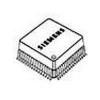
PEF82912FV14XP Lantiq, PEF82912FV14XP Datasheet - Page 107

PEF82912FV14XP
Manufacturer Part Number
PEF82912FV14XP
Description
Manufacturer
Lantiq
Datasheet
1.PEF82912FV14XP.pdf
(240 pages)
Specifications of PEF82912FV14XP
Number Of Line Interfaces
1
Control Interface
HDLC
Lead Free Status / Rohs Status
Supplier Unconfirmed
- Current page: 107 of 240
- Download datasheet (4Mb)
PEF 82912/82913
Functional Description
2.4.10.5 Description of the NT-States
The following states are used:
Alerting
The wake-up signal TN is transmitted for a period of T11 either in response to a received
wake-up signal TL or to start an activation procedure on the LT-side.
Alerting 1
“Alerting 1” state is entered when a wake-up tone was received in the “Receive Reset”
state and the deactivation procedure on the NT-side was not yet finished. The
transmission of wake-up tone TN is started.
Analog Loop-Back
Transparency is achieved in both directions of transmission. This state can be left by
making use of any unconditional command.
Deactivated
Only in state Deactivated the device may enter the power-down mode.
EC Training
The signal SN1 is transmitted on the U-interface to allow the NT-receiver to update the
EC-coefficients. The automatic gain control (AGC), the timing recovery and the EQ
updating algorithm are disabled.
EC-Training 1
The “EC-Training 1” state is entered if transmission of signal SN1 has to be started and
the deactivation procedure on the NT-side is not yet finished.
EC-Training AL
The signal SN1 is transmitted on the U-interface to allow the NT-receiver to update the
EC-coefficients. The automatic gain control (AGC), the timing recovery and the EQ
updating algorithm are disabled.
EQ-Training
The receiver waits for signal SL1 or SL2 to be able to update the AGC, to recover the
timing phase, to detect the synch-word (SW), and to update the EQ-coefficients.
Data Sheet
93
2001-03-30
Related parts for PEF82912FV14XP
Image
Part Number
Description
Manufacturer
Datasheet
Request
R

Part Number:
Description:
Manufacturer:
Lantiq
Datasheet:

Part Number:
Description:
Manufacturer:
Lantiq
Datasheet:

Part Number:
Description:
Manufacturer:
Lantiq
Datasheet:


