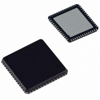
AD9911BCPZ Analog Devices Inc, AD9911BCPZ Datasheet - Page 2

AD9911BCPZ
Manufacturer Part Number
AD9911BCPZ
Description
IC DDS 500MSPS DAC 10BIT 56LFCSP
Manufacturer
Analog Devices Inc
Datasheet
1.AD9911BCPZ-REEL7.pdf
(44 pages)
Specifications of AD9911BCPZ
Resolution (bits)
10 b
Master Fclk
500MHz
Tuning Word Width (bits)
32 b
Voltage - Supply
1.71 V ~ 1.96 V
Operating Temperature
-40°C ~ 85°C
Mounting Type
Surface Mount
Package / Case
56-LFCSP
Transmitting Current
73mA
Data Rate
800Mbps
Rf Ic Case Style
LFCSP
No. Of Pins
56
Supply Voltage Range
1.71V To 1.89V, 3.135V To 3.465V
Operating Temperature Range
-40°C To +85°C
Msl
MSL 3 - 168 Hours
Lead Free Status / RoHS Status
Lead free / RoHS Compliant
For Use With
AD9911/PCBZ - BOARD EVAL FOR AD9911AD9911/PCB - BOARD EVAL FOR AD9911
Lead Free Status / Rohs Status
Compliant
Available stocks
Company
Part Number
Manufacturer
Quantity
Price
Company:
Part Number:
AD9911BCPZ
Manufacturer:
NXP
Quantity:
173
Part Number:
AD9911BCPZ
Manufacturer:
ADI/亚德诺
Quantity:
20 000
AD9911
TABLE OF CONTENTS
Features .............................................................................................. 1
Applications....................................................................................... 1
General Description ......................................................................... 1
Revision History ............................................................................... 2
Functional Block Diagram .............................................................. 3
Specifications..................................................................................... 4
Absolute Maximum Ratings............................................................ 9
Pin Configuration and Function Descriptions........................... 10
Typical Performance Characteristics ........................................... 12
Application Circuits ....................................................................... 17
Theory of Operation ...................................................................... 18
Modes of Operation ....................................................................... 19
REVISION HISTORY
5/06—Revision 0: Initial Version
ESD Caution.................................................................................. 9
Equivalent Input and Output Circuits....................................... 9
Primary DDS Core ..................................................................... 18
SpurKiller/Multitone Mode and Test-Tone Modulation....... 18
D/A Converter ............................................................................ 18
Single-Tone Mode ...................................................................... 19
SpurKiller/Multitone Mode ...................................................... 19
Test-tone Mode ........................................................................... 20
Reference Clock Modes ............................................................. 20
Scalable DAC Reference Current Control Mode ................... 21
Power-Down Functions............................................................. 21
Shift Keying Modulation ........................................................... 21
Shift Keying Modulation Using SDIO Pins for RU/RD ........ 23
Linear Sweep (Shaped) Modulation Mode ............................. 23
Linear Sweep No Dwell Mode .................................................. 25
Rev. 0 | Page 2 of 44
Synchronizing Multiple AD9911 Devices................................... 28
I/O Port............................................................................................ 30
Register Maps.................................................................................. 35
Control Register Descriptions ...................................................... 38
Outline Dimensions ....................................................................... 41
Sweep and Phase Accumulator Clearing Functions .............. 26
Output Amplitude Control ....................................................... 26
Operation .................................................................................... 28
Automatic Mode Synchronization ........................................... 28
Manual Software Mode Synchronization................................ 28
Manual Hardware Mode Synchronization.............................. 28
I/O_Update, SYNC_CLK, and System Clock
Relationships............................................................................... 29
Overview ..................................................................................... 30
Instruction Byte Description .................................................... 30
I/O Port Pin Description........................................................... 31
I/O Port Function Description ................................................. 31
MSB/LSB Transfer Description ................................................ 31
I/O Modes of Operation............................................................ 31
Control Register Map ................................................................ 35
Channel Register Map ............................................................... 36
Profile Register Map................................................................... 37
Channel Select Register (CSR) ................................................. 38
Channel Function Register (CFR) Description...................... 39
Ordering Guide .......................................................................... 41


