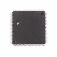
DP83953VUL National Semiconductor, DP83953VUL Datasheet - Page 43

DP83953VUL
Manufacturer Part Number
DP83953VUL
Description
IC CTRLR RIC REPEATER 160-PQFP
Manufacturer
National Semiconductor
Datasheet
1.DP83953VUL.pdf
(90 pages)
Specifications of DP83953VUL
Controller Type
Ethernet Repeater Interface Controller
Interface
IEEE 802.3
Voltage - Supply
4.75 V ~ 5.25 V
Current - Supply
870mA
Operating Temperature
0°C ~ 70°C
Mounting Type
Surface Mount
Package / Case
160-MQFP, 160-PQFP
Lead Free Status / RoHS Status
Contains lead / RoHS non-compliant
Other names
*DP83953VUL
Available stocks
Company
Part Number
Manufacturer
Quantity
Price
Company:
Part Number:
DP83953VUL
Manufacturer:
HJC
Quantity:
2 010
Company:
Part Number:
DP83953VUL
Manufacturer:
Texas Instruments
Quantity:
10 000
5.0 HUB MANAGEMENT SUPPORT
Collision Bit Timer
The Collision Timer counts, in bit times, the time between
the start of repetition of the packet and the detection of the
packet's first collision. When a collision occurs, the Colli-
sion counter increments as the packet repeats and freezes.
The value in the counter is only valid when the collision bit
"COL" in [PSR(1)] is set.
Repeat Byte Counter
The Repeat Byte Counter is a 16 bit counter that can per-
form two functions. In cases where the transmitted packet
possesses an SFD, the byte counter counts the number of
received bytes after the SFD field. Alternatively, if no SFD
is repeated, the counter reflects the length of the packet
(counted in bytes) starting at the beginning of the preamble
field. When performing the latter function, the counter is
shortened to 7 bits when MPS =0 in the GSR register.
Thus, the maximum count value is 127 bytes. The counter
is shortened to 11 bits when MPS =1 in the GSR register.
In this configuration, the maximum received byte count
changes to 2048 bytes. The mode of counting is indicated
by the "NSFD" bit in [PSR(2)]. In order to check if the
received packet was genuinely a Non-SFD packet, the sta-
tus of the COL bit should be checked. During collisions
SFD fields may be lost or created, Management software
should be robust to this kind of behavior.
Inter Frame Gap (IFG) Bit Timer
The IFG counter counts, in bit times, the period in between
repeater transmissions. The IFG counter increments when-
ever the RIC2A is not transmitting a packet. If the IFG is
long, i.e., greater than 255 bit times, the counter holds this
value. Thus a count value equal to 255 should be inter-
preted as 255 or more bit times.
(Continued)
43
5.4 Description of Hardware Connection for Man-
agement Interface
The RIC2A has been designed so that it may be connected
to the management bus directly or to external bus trans-
ceivers. External bus transceivers are advantageous in
larger repeaters because system backplanes are often
heavily loaded beyond the drive capabilities of the on-chip
bus drivers.
The unidirectional nature of information transfer on the
MCRS, MRXD and MRXC signals, means a single open
drain output pin is adequate for each of these signals. The
Management Enable (MEN) RIC2A output pin performs the
function of a drive enable for an external bus transceiver if
one is required.
In common with the Inter-RIC bus signals (ACTN, ANYXN,
COLN and IRE) the MCRS active level asserted by the
MCRS output is determined by the state of the BINV Mode
Load configuration bit.
www.national.com


