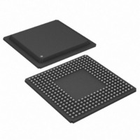
DS21FF44 Maxim Integrated Products, DS21FF44 Datasheet - Page 25

DS21FF44
Manufacturer Part Number
DS21FF44
Description
IC FRAMER E1 4X4 16CH 300-BGA
Manufacturer
Maxim Integrated Products
Datasheet
1.DS21FT44N.pdf
(117 pages)
Specifications of DS21FF44
Controller Type
E1 Framer
Interface
Parallel/Serial
Voltage - Supply
2.97 V ~ 3.63 V
Current - Supply
300mA
Operating Temperature
0°C ~ 70°C
Mounting Type
Surface Mount
Package / Case
300-BGA
Lead Free Status / RoHS Status
Contains lead / RoHS non-compliant
Available stocks
Company
Part Number
Manufacturer
Quantity
Price
Signal Name:
Signal Description:
Signal Type:
RD* and DS* are active-low signals. Note: DS is active high when MUX = 1. See bus timing diagrams in
Section 23.
Signal Name:
Signal Description:
Signal Type:
Selects which of the four framers to be accessed.
Signal Name:
Signal Description:
Signal Type:
Must be low to read or write to the device. CS* is an active low signal.
Signal Name:
Signal Description:
Signal Type:
WR* is an active-low signal.
TEST ACCESS PORT PINS
Signal Name:
Signal Description:
Signal Type:
Set high to tri-state all output and I/O pins (including the parallel control port). Set low for normal
operation. Useful in board level testing.
Signal Name:
Signal Description:
Signal Type:
This signal is used to asynchronously reset the test access port controller. At power-up, JTRST* must be
set low and then high. This action sets the device into the boundary scan bypass mode allowing normal
device operation. If boundary scan is not used, this pin should be held low. This function is available
when FMS = 0. FMS is connected to ground for the DS21FF44/DS21FT44.
Signal Name:
Signal Description:
Signal Type:
This pin is sampled on the rising edge of JTCLK and is used to place the test port into the various defined
IEEE 1149.1 states. If not used, this pin should be pulled high. This function is available when FMS = 0.
FMS is connected to ground for the DS21FF44/DS21FT44.
Signal Name:
Signal Description:
Signal Type:
This signal is used to shift data into JTDI on the rising edge and out of JTDO on the falling edge. If not
used, this pin should be connected to VSS. This function is available when FMS = 0.
RD* (DS*)
Read Input (Data Strobe)
Input
FS0 and FS1
Framer Selects
Input
CS*
Chip Select
Input
WR* (R/W*)
Write Input (Read/Write)
Input
Test
3–State Control
Input
JTRST*
IEEE 1149.1 Test Reset
Input
JTMS
IEEE 1149.1 Test Mode Select
Input
JTCLK
IEEE 1149.1 Test Clock Signal
Input
25 of 117


