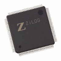
EZ80190AZ050EG Zilog, EZ80190AZ050EG Datasheet - Page 99

EZ80190AZ050EG
Manufacturer Part Number
EZ80190AZ050EG
Description
IC WEBSERVER 50MHZ XTEMP 100LQFP
Manufacturer
Zilog
Datasheet
1.EZ80190AZ050SG.pdf
(221 pages)
Specifications of EZ80190AZ050EG
Processor Type
eZ80
Features
High Speed, Single-Cycle Instruction-Fetch
Speed
50MHz
Voltage
3.3V
Mounting Type
Surface Mount
Package / Case
100-LQFP
Processor Series
EZ80190x
Core
eZ80
Data Bus Width
8 bit
Program Memory Type
ROMLess
Data Ram Size
8 KB
Interface Type
I2C, IrDA, SPI, UART
Maximum Clock Frequency
50 MHz
Number Of Programmable I/os
32
Number Of Timers
6
Operating Supply Voltage
3 V to 3.6 V
Maximum Operating Temperature
+ 70 C
Mounting Style
SMD/SMT
Minimum Operating Temperature
0 C
Lead Free Status / RoHS Status
Lead free / RoHS Compliant
Other names
269-3865
EZ80190AZ050EG
EZ80190AZ050EG
Available stocks
Company
Part Number
Manufacturer
Quantity
Price
Company:
Part Number:
EZ80190AZ050EG
Manufacturer:
TYCO
Quantity:
120
Company:
Part Number:
EZ80190AZ050EG
Manufacturer:
Zilog
Quantity:
70
- Current page: 99 of 221
- Download datasheet (4Mb)
SPI Registers
PS006614-1208
SPI Control Register
Table 39. SPI Control Register
Bit
Reset
CPU Access
Note: R = Read Only; R/W = Read/Write.
Bit
Position
7
IRQ_EN
6
5
SPI_EN
4
MASTER_EN
3
CPOL
2
CPHA
[1:0]
There are four registers in the Serial Peripheral Interface which provide control, status,
and data storage functions. These registers are called the SPI Control register (SPIx_CTL),
SPI Status register (SPIx_SR), SPI Receive Buffer register (SPIx_RBR), and SPI Transmit
Shift register (SPIx_TSR), where the x in each register name is either 0 or 1 depending on
which UZI device the SPI is located within. The SPI registers are described in this section.
The SPI Control Register, listed in
eral interface.
Value Description
0
1
0
0
1
0
1
0
1
0
1
00b
R/W
The SPI system interrupt is disabled.
The SPI system interrupt is enabled.
Reserved—must be 0.
The SPI is disabled.
The SPI is enabled.
When enabled, the SPI operates as a slave.
When enabled, the SPI operates as a master.
The master SCK pin idles in a Low (0) state.
The master SCK pin idles in a High (1) state.
SS must go High after a transfer of every byte of data.
SS can remain Low to transfer any number of data bytes.
Reserved—must be 0.
7
0
R
6
0
R/W
Table
5
0
(SPI0_CTL = B6h, SPI1_CTL = BAh)
39, is used to control and set up the serial periph-
R/W
4
0
R/W
3
0
R/W
2
1
Product Specification
Serial Peripheral Interface
R
1
0
R
0
0
eZ80190
89
Related parts for EZ80190AZ050EG
Image
Part Number
Description
Manufacturer
Datasheet
Request
R

Part Number:
Description:
Communication Controllers, ZILOG INTELLIGENT PERIPHERAL CONTROLLER (ZIP)
Manufacturer:
Zilog, Inc.
Datasheet:

Part Number:
Description:
KIT DEV FOR Z8 ENCORE 16K TO 64K
Manufacturer:
Zilog
Datasheet:

Part Number:
Description:
KIT DEV Z8 ENCORE XP 28-PIN
Manufacturer:
Zilog
Datasheet:

Part Number:
Description:
DEV KIT FOR Z8 ENCORE 8K/4K
Manufacturer:
Zilog
Datasheet:

Part Number:
Description:
KIT DEV Z8 ENCORE XP 28-PIN
Manufacturer:
Zilog
Datasheet:

Part Number:
Description:
DEV KIT FOR Z8 ENCORE 4K TO 8K
Manufacturer:
Zilog
Datasheet:

Part Number:
Description:
CMOS Z8 microcontroller. ROM 16 Kbytes, RAM 256 bytes, speed 16 MHz, 32 lines I/O, 3.0V to 5.5V
Manufacturer:
Zilog, Inc.
Datasheet:

Part Number:
Description:
Low-cost microcontroller. 512 bytes ROM, 61 bytes RAM, 8 MHz
Manufacturer:
Zilog, Inc.
Datasheet:

Part Number:
Description:
Z8 4K OTP Microcontroller
Manufacturer:
Zilog, Inc.
Datasheet:

Part Number:
Description:
CMOS SUPER8 ROMLESS MCU
Manufacturer:
Zilog, Inc.
Datasheet:

Part Number:
Description:
SL1866 CMOSZ8 OTP Microcontroller
Manufacturer:
Zilog, Inc.
Datasheet:

Part Number:
Description:
SL1866 CMOSZ8 OTP Microcontroller
Manufacturer:
Zilog, Inc.
Datasheet:

Part Number:
Description:
OTP (KB) = 1, RAM = 125, Speed = 12, I/O = 14, 8-bit Timers = 2, Comm Interfaces Other Features = Por, LV Protect, Voltage = 4.5-5.5V
Manufacturer:
Zilog, Inc.
Datasheet:

Part Number:
Description:
Manufacturer:
Zilog, Inc.
Datasheet:


