MPC8360EZUAJDGA Freescale Semiconductor, MPC8360EZUAJDGA Datasheet - Page 52
MPC8360EZUAJDGA
Manufacturer Part Number
MPC8360EZUAJDGA
Description
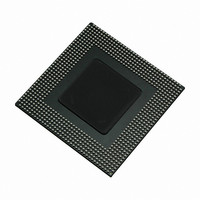
IC MPU POWERQUICC II PRO 740TBGA
Manufacturer
Freescale Semiconductor
Datasheet
1.MPC8360CZUAJDG.pdf
(108 pages)
Specifications of MPC8360EZUAJDGA
Processor Type
MPC83xx PowerQUICC II Pro 32-Bit
Speed
533MHz
Voltage
1.2V
Mounting Type
Surface Mount
Package / Case
740-TBGA
Processor Series
MPC8xxx
Core
e300
Data Bus Width
32 bit
Development Tools By Supplier
MPC8360E-RDK
Maximum Clock Frequency
533 MHz
Maximum Operating Temperature
+ 105 C
Mounting Style
SMD/SMT
I/o Voltage
1.8 V, 2.5 V, 3.3 V
Minimum Operating Temperature
0 C
For Use With
MPC8360EA-MDS-PB - KIT APPLICATION DEV 8360 SYSTEMMPC8360E-RDK - BOARD REFERENCE DESIGN FOR MPC
Lead Free Status / RoHS Status
Lead free / RoHS Compliant
Features
-
Lead Free Status / Rohs Status
Lead free / RoHS Compliant
Available stocks
Company
Part Number
Manufacturer
Quantity
Price
Company:

Part Number:
MPC8360EZUAJDGA
Manufacturer:
Freescale Semiconductor
Quantity:
10 000


I
11 I
This section describes the DC and AC electrical characteristics for the I
MPC8360E/58E.
11.1
Table 44
11.2
Table 45
52
At recommended operating conditions with OV
All values refer to V
2
Input high voltage level
Input low voltage level
Low level output voltage
Output fall time from V
capacitance from 10 to 400 pF
Pulse width of spikes which must be suppressed by the input
filter
Capacitance for each I/O pin
Input current (0 V ≤ V
Notes:
1. Output voltage (open drain or open collector) condition = 3 mA sink current.
2. C
3. Refer to the MPC8360E Integrated Communications Processor Family Reference Manual for information on the digital filter
4. I/O pins will obstruct the SDA and SCL lines if OV
SCL clock frequency
Low period of the SCL clock
High period of the SCL clock
Setup time for a repeated START condition
Hold time (repeated) START condition (after this period, the first
clock pulse is generated)
Data setup time
C
used.
MPC8360E/MPC8358E PowerQUICC II Pro Processor Revision 2.x TBGA Silicon Hardware Specifications, Rev. 4
B
= capacitance of one bus line in pF.
2
provides the DC electrical characteristics for the I
provides the AC timing parameters for the I
I
I
C
2
2
C AC Electrical Specifications
C DC Electrical Characteristics
IH
(min) and V
IN
IH
≤ OV
(min) to V
Parameter
Parameter
DD
IL
(max) levels (see
)
IL
(max) with a bus
Table 44. I
Table 45. I
DD
of 3.3 V ± 10%.
Table
2
2
C DC Electrical Characteristics
C AC Electrical Specifications
DD
44).
is switched off.
2
Symbol
t
C interface of the device.
t
I2KLKV
I2KHKL
V
V
V
I
C
IN
OL
IH
IL
I
2
Symbol
C interface of the device.
t
t
t
I2SVKH
I2DVKH
I2SXKL
t
t
I2CH
f
I2CL
I2C
20 + 0.1 × C
0.7 × OV
1
–0.3
Min
—
—
0
0
2
DD
C interface of the
B
Min
100
1.3
0.6
0.6
0.6
0
OV
0.3 × OV
DD
Max
250
±10
0.4
50
10
+ 0.3
Freescale Semiconductor
DD
Max
400
—
—
—
—
—
Unit
pF
μA
ns
ns
V
V
V
Notes
Unit
kHz
—
—
—
μs
μs
μs
μs
ns
1
2
3
4
Related parts for MPC8360EZUAJDGA
Image
Part Number
Description
Manufacturer
Datasheet
Request
R

Part Number:
Description:
Mpc8360e Powerquicc Ii Pro Family
Manufacturer:
Freescale Semiconductor, Inc
Datasheet:

Part Number:
Description:
BOARD REFERENCE DESIGN FOR MPC
Manufacturer:
Freescale Semiconductor
Datasheet:

Part Number:
Description:
BOARD PROCESSOR FOR MPC8360E
Manufacturer:
Freescale Semiconductor
Datasheet:
Part Number:
Description:
Manufacturer:
Freescale Semiconductor, Inc
Datasheet:
Part Number:
Description:
Manufacturer:
Freescale Semiconductor, Inc
Datasheet:
Part Number:
Description:
Manufacturer:
Freescale Semiconductor, Inc
Datasheet:
Part Number:
Description:
Manufacturer:
Freescale Semiconductor, Inc
Datasheet:
Part Number:
Description:
Manufacturer:
Freescale Semiconductor, Inc
Datasheet:
Part Number:
Description:
Manufacturer:
Freescale Semiconductor, Inc
Datasheet:
Part Number:
Description:
Manufacturer:
Freescale Semiconductor, Inc
Datasheet:
Part Number:
Description:
Manufacturer:
Freescale Semiconductor, Inc
Datasheet:
Part Number:
Description:
Manufacturer:
Freescale Semiconductor, Inc
Datasheet:
Part Number:
Description:
Manufacturer:
Freescale Semiconductor, Inc
Datasheet:
Part Number:
Description:
Manufacturer:
Freescale Semiconductor, Inc
Datasheet:
Part Number:
Description:
Manufacturer:
Freescale Semiconductor, Inc
Datasheet: