DLP-245PB-G DLP Design Inc, DLP-245PB-G Datasheet - Page 8
DLP-245PB-G
Manufacturer Part Number
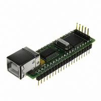
DLP-245PB-G
Description
MODULE USB-MCU FT245RL W/16F877A
Manufacturer
DLP Design Inc
Datasheet
1.DLP-245PB-G.pdf
(16 pages)
Specifications of DLP-245PB-G
Module/board Type
Development Board
Interface Type
USB
Data Bus Width
8 bit
Operating Supply Voltage
5 V
Product
Interface Modules
For Use With/related Products
USB
Lead Free Status / RoHS Status
Lead free / RoHS Compliant
Lead Free Status / RoHS Status
Lead free / RoHS Compliant, Lead free / RoHS Compliant
Other names
813-1004
Available stocks
Company
Part Number
Manufacturer
Quantity
Price
Company:

Part Number:
DLP-245PB-G
Manufacturer:
DLP Design
Quantity:
135


TOKEN I/O COMMAND SET
0xA5 – Line In – Reads the state of a single port pin
Parameters:
Returns:
Function:
Example:
0xA6 – Line Out - Sets a single port pin high or low
Parameters:
Returns:
Function:
Example:
0xA7 – Return Board ID
Parameters:
Returns:
Function:
Example:
0xA8 – Setup A/D
Parameters:
Returns:
Function:
Example:
V2.3
Port – Select from available port pins (PIN_A3, PIN_B0, etc)
1 Byte: State of the port pin (0 or 1)
This function will read the state of a single port pin. If the data direction for the
pin selected was set to output, the direction is first set to input.
0x2, 0xA5, 0x2B, 0x8C - Reads the current state of port pin PIN_A3.
Port – Select from available port pins (PIN_A3, PIN_B3, etc)
State – 0 or 1
Undefined
This function will change the output state of a single port pin. If the data direction
for the pin selected was set to input, the direction is first set to output.
0x3, 0xA6, 0x2B, 0x1, 0x8F – Sets port pin PIN_A3 high.
None
5 bytes: “245PB”
This function will return the ID of the board currently opened.
0x1, 0xA7, A6 – Reads the board ID.
Port Configuration – Selects analog port configuration. (See command 0xA8 in
the example firmware for options.)
A/D Conversion Clock – Select the source for the A/D conversion clock. (See
command 0xA8 in the example firmware for options.)
Undefined
This function will select the source for the A/D conversion clock. (Refer to the
datasheet for the 16F877A for a detailed explanation of the conversion clock.)
0x3, 0xA8, 0x0, 0x7, 0xAC – Sets all available A/D inputs on the DLP-245PB-G
to analog mode (0x0) and selects the internal A/D clock (0x7).
Page 8 of
15
February 2007
Related parts for DLP-245PB-G
Image
Part Number
Description
Manufacturer
Datasheet
Request
R

Part Number:
Description:
MODULE USB-TO-TTL SRL UART CONV
Manufacturer:
DLP Design Inc
Datasheet:

Part Number:
Description:
MODULE USB-TO-TTL PARL FIFO CONV
Manufacturer:
DLP Design Inc
Datasheet:

Part Number:
Description:
KIT DEV DLP LIGHTCOMANDER
Manufacturer:
Logic
Datasheet:

Part Number:
Description:
MODULE DATA-ACQUISITION 8-CH
Manufacturer:
DLP Design Inc
Datasheet:

Part Number:
Description:
MODULE DATA-ACQUISITION 20-CH
Manufacturer:
DLP Design Inc
Datasheet:

Part Number:
Description:
RFID READER/WRITER SNGL-CH OEM
Manufacturer:
DLP Design Inc
Datasheet:

Part Number:
Description:
Interface Modules & Development Tools DLP-245PL PACKAGED w/CCS Compiler
Manufacturer:
DLP Design Inc

Part Number:
Description:
Interface Modules & Development Tools DLP-245PB-G BOARD + CCS Compiler
Manufacturer:
DLP Design Inc
Datasheet:

Part Number:
Description:
Interface Modules & Development Tools DLP-TILT SENSOR ACCEL VIBRATION
Manufacturer:
DLP Design Inc

Part Number:
Description:
MODULE USB-TO-FPGA TRAINING TOOL
Manufacturer:
DLP Design Inc
Datasheet:

Part Number:
Description:
MODULE USB-MCU FT232R W/18F2410
Manufacturer:
DLP Design Inc
Datasheet:

Part Number:
Description:
MODULE USB-MCU FT245RL W/SX48
Manufacturer:
DLP Design Inc
Datasheet:

Part Number:
Description:
MODULE USB-MCU FT2232D W/16F877A
Manufacturer:
DLP Design Inc
Datasheet:

Part Number:
Description:
MODULE USB-TO-FPGA SPARTAN3
Manufacturer:
DLP Design Inc
Datasheet:

Part Number:
Description:
MOD USB-MCU FT245RL W/18LF8722
Manufacturer:
DLP Design Inc
Datasheet: