DLP-245PB-G DLP Design Inc, DLP-245PB-G Datasheet - Page 5
DLP-245PB-G
Manufacturer Part Number
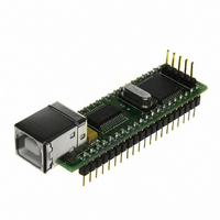
DLP-245PB-G
Description
MODULE USB-MCU FT245RL W/16F877A
Manufacturer
DLP Design Inc
Datasheet
1.DLP-245PB-G.pdf
(16 pages)
Specifications of DLP-245PB-G
Module/board Type
Development Board
Interface Type
USB
Data Bus Width
8 bit
Operating Supply Voltage
5 V
Product
Interface Modules
For Use With/related Products
USB
Lead Free Status / RoHS Status
Lead free / RoHS Compliant
Lead Free Status / RoHS Status
Lead free / RoHS Compliant, Lead free / RoHS Compliant
Other names
813-1004
Available stocks
Company
Part Number
Manufacturer
Quantity
Price
Company:

Part Number:
DLP-245PB-G
Manufacturer:
DLP Design
Quantity:
135


QUICK START GUIDE
This guide requires the use of a Windows 98/2000/XP PC that is equipped with a USB port.
1. Download the DLL (D2XX) version of the device drivers from either dlpdesign.com or
2. The DLP-245PB-G can be configured to receive its operating power from the USB port or
3. Connect the DLP-245PB-G board to the PC via a standard A-B, 6-foot USB cable. This
The DLP-245PB-G is shipped with default VID, PID, etc. values programmed into the EEPROM
memory. You only need to run MPROG if you want to change the default values.
At this point, the DLP-245PB-G is ready for use. Note that the DLP-245PB-G will appear
non-responsive if data sent from the host PC is not read from the FT245RL device by the
16F877A microcontroller.
If changing drivers from the VCP to the DLL type (or vice versa), you must first uninstall the
currently loaded drivers. To accomplish this, first disconnect the DLP-245PB-G adapter from the
host computer and then use Add-Remove-Programs in Control Panel.
V2.3
ftdichip.com. Unzip the drivers onto a blank floppy disk or into a folder on the hard drive.
from user electronics. Pins 18, 19, and 20 allow for this configuration. (Refer to the Pinout
Description in the next section for a detailed description of the DLP-245PB-G electrical
interface.)
Note: The board will not operate until a power source has been selected as mentioned in
Step 2.
action initiates the loading of the USB drivers. When prompted, select the folder where the
DLL version of the device drivers was stored in Step 1. Windows will then complete the
installation of the device drivers for the DLP-245PB-G board. The next time the DLP-245PB-
G board is attached, the host PC will immediately load the correct drivers without any
prompting. Reboot the PC if prompted to do so.
Page 5 of
15
February 2007
Related parts for DLP-245PB-G
Image
Part Number
Description
Manufacturer
Datasheet
Request
R

Part Number:
Description:
MODULE USB-TO-TTL SRL UART CONV
Manufacturer:
DLP Design Inc
Datasheet:

Part Number:
Description:
MODULE USB-TO-TTL PARL FIFO CONV
Manufacturer:
DLP Design Inc
Datasheet:

Part Number:
Description:
KIT DEV DLP LIGHTCOMANDER
Manufacturer:
Logic
Datasheet:

Part Number:
Description:
MODULE DATA-ACQUISITION 8-CH
Manufacturer:
DLP Design Inc
Datasheet:

Part Number:
Description:
MODULE DATA-ACQUISITION 20-CH
Manufacturer:
DLP Design Inc
Datasheet:

Part Number:
Description:
RFID READER/WRITER SNGL-CH OEM
Manufacturer:
DLP Design Inc
Datasheet:

Part Number:
Description:
Interface Modules & Development Tools DLP-245PL PACKAGED w/CCS Compiler
Manufacturer:
DLP Design Inc

Part Number:
Description:
Interface Modules & Development Tools DLP-245PB-G BOARD + CCS Compiler
Manufacturer:
DLP Design Inc
Datasheet:

Part Number:
Description:
Interface Modules & Development Tools DLP-TILT SENSOR ACCEL VIBRATION
Manufacturer:
DLP Design Inc

Part Number:
Description:
MODULE USB-TO-FPGA TRAINING TOOL
Manufacturer:
DLP Design Inc
Datasheet:

Part Number:
Description:
MODULE USB-MCU FT232R W/18F2410
Manufacturer:
DLP Design Inc
Datasheet:

Part Number:
Description:
MODULE USB-MCU FT245RL W/SX48
Manufacturer:
DLP Design Inc
Datasheet:

Part Number:
Description:
MODULE USB-MCU FT2232D W/16F877A
Manufacturer:
DLP Design Inc
Datasheet:

Part Number:
Description:
MODULE USB-TO-FPGA SPARTAN3
Manufacturer:
DLP Design Inc
Datasheet:

Part Number:
Description:
MOD USB-MCU FT245RL W/18LF8722
Manufacturer:
DLP Design Inc
Datasheet: