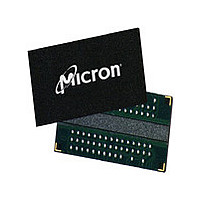
MT47H32M16HR-3:FTR Micron Technology Inc, MT47H32M16HR-3:FTR Datasheet - Page 6

MT47H32M16HR-3:FTR
Manufacturer Part Number
MT47H32M16HR-3:FTR
Description
Manufacturer
Micron Technology Inc
Type
DDR2 SDRAMr
Datasheet
1.MT47H32M16HR-3FTR.pdf
(131 pages)
Specifications of MT47H32M16HR-3:FTR
Organization
32Mx16
Density
512Mb
Address Bus
15b
Access Time (max)
450ps
Maximum Clock Rate
667MHz
Operating Supply Voltage (typ)
1.8V
Package Type
FBGA
Operating Temp Range
0C to 85C
Operating Supply Voltage (max)
1.9V
Operating Supply Voltage (min)
1.7V
Supply Current
250mA
Pin Count
84
Mounting
Surface Mount
Operating Temperature Classification
Commercial
Lead Free Status / Rohs Status
Compliant
Available stocks
Company
Part Number
Manufacturer
Quantity
Price
Part Number:
MT47H32M16HR-3:FTR
Manufacturer:
MICRON/镁光
Quantity:
20 000
512Mb: x4, x8, x16 DDR2 SDRAM
Features
Figure 51: Bank Read – Without Auto Precharge ............................................................................................. 97
Figure 52: Bank Read – with Auto Precharge ................................................................................................... 98
t
t
Figure 53: x4, x8 Data Output Timing –
DQSQ,
QH, and Data Valid Window .................................................. 99
t
t
Figure 54: x16 Data Output Timing –
DQSQ,
QH, and Data Valid Window ..................................................... 100
t
t
Figure 55: Data Output Timing –
AC and
DQSCK ......................................................................................... 101
Figure 56: Write Burst ................................................................................................................................... 103
Figure 57: Consecutive WRITE-to-WRITE ...................................................................................................... 104
Figure 58: Nonconsecutive WRITE-to-WRITE ................................................................................................ 104
Figure 59: WRITE Interrupted by WRITE ....................................................................................................... 105
Figure 60: WRITE-to-READ ........................................................................................................................... 106
Figure 61: WRITE-to-PRECHARGE ................................................................................................................ 107
Figure 62: Bank Write – Without Auto Precharge ............................................................................................ 108
Figure 63: Bank Write – with Auto Precharge ................................................................................................. 109
Figure 64: WRITE – DM Operation ................................................................................................................ 110
Figure 65: Data Input Timing ........................................................................................................................ 111
Figure 66: Refresh Mode ............................................................................................................................... 112
Figure 67: Self Refresh .................................................................................................................................. 114
Figure 68: Power-Down ................................................................................................................................ 116
Figure 69: READ-to-Power-Down or Self Refresh Entry .................................................................................. 118
Figure 70: READ with Auto Precharge-to-Power-Down or Self Refresh Entry .................................................. 118
Figure 71: WRITE-to-Power-Down or Self Refresh Entry ................................................................................ 119
Figure 72: WRITE with Auto Precharge-to-Power-Down or Self Refresh Entry ................................................. 119
Figure 73: REFRESH Command-to-Power-Down Entry ................................................................................. 120
Figure 74: ACTIVATE Command-to-Power-Down Entry ................................................................................ 120
Figure 75: PRECHARGE Command-to-Power-Down Entry ............................................................................ 121
Figure 76: LOAD MODE Command-to-Power-Down Entry ............................................................................ 121
Figure 77: Input Clock Frequency Change During Precharge Power-Down Mode ........................................... 122
Figure 78: RESET Function ........................................................................................................................... 124
Figure 79: ODT Timing for Entering and Exiting Power-Down Mode .............................................................. 126
Figure 80: Timing for MRS Command to ODT Update Delay .......................................................................... 127
Figure 81: ODT Timing for Active or Fast-Exit Power-Down Mode ................................................................. 127
Figure 82: ODT Timing for Slow-Exit or Precharge Power-Down Modes ......................................................... 128
Figure 83: ODT Turn-Off Timings When Entering Power-Down Mode ............................................................ 128
Figure 84: ODT Turn-On Timing When Entering Power-Down Mode ............................................................. 129
Figure 85: ODT Turn-Off Timing When Exiting Power-Down Mode ............................................................... 130
Figure 86: ODT Turn-On Timing When Exiting Power-Down Mode ................................................................ 131
6
PDF: 09005aef82f1e6e2
Micron Technology, Inc. reserves the right to change products or specifications without notice.
512MbDDR2.pdf - Rev. Q 10/10 EN
© 2004 Micron Technology, Inc. All rights reserved.


