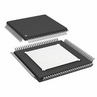
AD9271BSVZRL-25 Analog Devices Inc, AD9271BSVZRL-25 Datasheet - Page 44

AD9271BSVZRL-25
Manufacturer Part Number
AD9271BSVZRL-25
Description
IC ADC OCT 12BIT 25MSPS 100-TQFP
Manufacturer
Analog Devices Inc
Datasheet
1.AD9271BSVZ-50.pdf
(60 pages)
Specifications of AD9271BSVZRL-25
Number Of Bits
12
Sampling Rate (per Second)
25M
Data Interface
Serial, SPI™
Number Of Converters
8
Power Dissipation (max)
1.06W
Voltage Supply Source
Single Supply
Operating Temperature
-40°C ~ 85°C
Mounting Type
Surface Mount
Package / Case
100-TQFP Exposed Pad
Power Dissipation Pd
150mW
Peak Reflow Compatible (260 C)
Yes
Supply Voltage
1.8V
Sample Rate
25 MSPS
Termination Type
SMD
Supply Voltage Max
1.9V
Input Channels Per Adc
8
Lead Free Status / RoHS Status
Lead free / RoHS Compliant
For Use With
AD9271-50EBZ - BOARD EVALUATION AD9271 50MSPS
Lead Free Status / RoHS Status
Lead free / RoHS Compliant, Lead free / RoHS Compliant
Available stocks
Company
Part Number
Manufacturer
Quantity
Price
Company:
Part Number:
AD9271BSVZRL-25
Manufacturer:
AD
Quantity:
1 140
Company:
Part Number:
AD9271BSVZRL-25
Manufacturer:
Analog Devices Inc
Quantity:
10 000
AD9271
QUICK START PROCEDURE
The following is a list of the default and optional settings when
using the AD9271 either on the evaluation board or at the
system level design.
If an evaluation board is not being used, follow only the SPI
controller steps.
When using the AD9271 evaluation board,
1.
2.
3.
When using the AD9271 evaluation board or system level design,
1.
2.
3.
Open ADC Analyzer on a PC, click Configuration , and
select the appropriate product configuration file.
If the correct product configuration file is not available,
choose a similar product configuration file or click Cancel
and create a new one. See the ADC Analyzer User Manual
located at www.analog.com/FIFO.
From the Config menu, choose Channel Select . To evaluate
Channel A on the ADC evaluation board, ensure that only
the Channel B checkbox in ADC Analyzer is selected.
Channel A through Channel D correspond to Channel B in
ADC Analyzer.
Channel E through Channel H correspond to Channel A in
ADC Analyzer.
Click SPI in ADC Analyzer to open the SPI controller
software. If prompted for a configuration file, select the
appropriate one. If not, look at the title bar of the window
to see which configuration is loaded. If necessary, choose
Cfg Open from the File menu and select the appropriate one.
Note that the CHIP ID(1) field may be filled in regardless of
whether the correct SPI controller configuration file is loaded.
Click New DUT (
In the Global tab of SPI Controller, find the CHIP
GRADE(2) box and use the drop-down menu to select
the correct speed grade.
In the ADCGlobal 0 tab of SPI Controller, find the
HIGHPASS(2B) box and select the Manual Tune box to
calibrate the antialiasing filter.
) in the SPI Controller software.
Rev. B | Page 44 of 60
4.
5.
6.
7.
8.
9.
In SPI Controller, select Controller Dialog from the
Config menu. In the PROGRAM CONTROL box, ensure
that Enable Auto Channel Update is selected and click OK .
In the Global tab of SPI Controller, find the DEVICE
INDEX(4/5) box. In the ADC column, click S so that the
adjustment in the next step applies to all channels.
In the ADC A tab of SPI Controller, find the OFFSET(10)
box and use the drop-down menu labeled Offset Adj to select
the correct LNA offset correction: 25 decimal for the 50 MSPS
speed grade, 26 decimal for the 40 MSPS speed grade, or
31 decimal for the 25 MSPS speed grade.
Click FFT (
Adjust the amplitude of the input signal so that the
fundamental is at the desired level. (Examine the Fund:
reading in the left panel of the ADC Analyzer FFT
window.) If the GAIN± pins voltage is low (near 0 V), it
may not be possible to reach full scale without distortion.
Use a higher gain setting or a lower input level to avoid
distortion.
Right-click the FFT plot and select Comments . Use this
box to record information such as the serial number of the
board, the channel, the input and clock frequencies, the
GAIN± pins voltage, and the date. Press the PRINT
SCREEN key and save the FFT screenshot if desired.
–100
–110
–120
–130
–10
–20
–30
–40
–50
–60
–70
–80
–90
0
0
Figure 74. Typical FFT, AD9271-50
5
) in Visual Analog.
FREQUENCY (MHz)
10
15
f
LNA = 6×
V
FILTER TUNED
HPF = 700kHz
IN
GAIN
= 3.5MHz @ –1dBFS
= 1V
20
2
5


