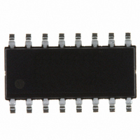
ICS307M-02ILFT IDT, Integrated Device Technology Inc, ICS307M-02ILFT Datasheet - Page 3

ICS307M-02ILFT
Manufacturer Part Number
ICS307M-02ILFT
Description
IC CLOCK SOURCE PROGR 16-SOIC
Manufacturer
IDT, Integrated Device Technology Inc
Type
Clock Generatorr
Datasheet
1.ICS307M-02LFT.pdf
(10 pages)
Specifications of ICS307M-02ILFT
Pll
Yes with Bypass
Input
Clock, Crystal
Output
LVCMOS
Number Of Circuits
1
Ratio - Input:output
2:2
Differential - Input:output
No/No
Frequency - Max
180MHz
Divider/multiplier
Yes/No
Voltage - Supply
3 V ~ 5.5 V
Operating Temperature
-40°C ~ 85°C
Mounting Type
Surface Mount
Package / Case
16-SOIC
Frequency-max
180MHz
Number Of Elements
1
Pll Input Freq (min)
2MHz
Pll Input Freq (max)
50MHz
Operating Supply Voltage (typ)
3.3/5V
Operating Temp Range
-40C to 85C
Package Type
SOIC N
Output Frequency Range
6 to 180MHz
Operating Supply Voltage (min)
3V
Operating Supply Voltage (max)
5.5V
Operating Temperature Classification
Industrial
Pin Count
16
Lead Free Status / RoHS Status
Lead free / RoHS Compliant
Other names
307M-02ILFT
800-1797-2
800-1797-2
Available stocks
Company
Part Number
Manufacturer
Quantity
Price
Company:
Part Number:
ICS307M-02ILFT
Manufacturer:
ADI
Quantity:
211
IDT™ / ICS™ SERIALLY PROGRAMMABLE CLOCK SOURCE
ICS307-01/-02
SERIALLY PROGRAMMABLE CLOCK SOURCE
Determining the Output Frequency
On power-up, the ICS307-01 on-chip registers can have
random values so almost any frequency may be output
from the part. CLK1 will always have some clock signal
present, but CLK2 could possibly be OFF (low).
The ICS307-02 on-chip registers are initially configured
to provide a x1 output clock on both the CLK1 and CLK2
outputs. The output frequency will be the same as the
input clock or crystal. This is useful if the ICS307 will
provide the initial system clock at power-up. Since this
feature is an advantage in most systems, the
ICS307-02 is recommended for new designs.
With programming, the user has full control in changing
the desired output frequency to any value over the
range shown in Table 1 on page 4. The output of the
ICS307 can be determined by the following equation:
The following operating ranges should be observed. For
the commercial temperature range:
CLK1Frequency
55MHz InputFrequency
Where:
200kHz
VCO Divider Word (VDW) = 4 to 511 (0, 1, 2, 3
are not permitted)
Reference Divider Word (RDW) = 1 to 127 (0 is
not permitted)
Output Divider = values on page 4
InputFrequency
--------------------------------------------- -
RDW
=
InputFrequency
+
2
2
VDW
------------------------
RDW
+
+
2
8
2
<
--------------------------------------------- -
400MHz
RDW
VDW
+
2
+
8
OD
3
And for the industrial temperature range:
To determine the best combination of VCO, reference,
and output dividers, see the online calculator at
www.idt.com
cmd-support@idt.com with the desired input crystal or
clock and the desired output frequency.
60MHz InputFrequency
200kHz
<
or contact IDT by sending an e-mail to
Input Frequency
------------------------------------------ -
RDW
+
SER PROG CLOCK SYNTHESIZER
2
2
VDW
------------------------
RDW
ICS307-01/-02 REV J 051310
+
+
8
2
<
360MHz


