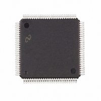
FPD85310VJD National Semiconductor, FPD85310VJD Datasheet - Page 24

FPD85310VJD
Manufacturer Part Number
FPD85310VJD
Description
IC CTRLR PANEL TIMING 100-TQFP
Manufacturer
National Semiconductor
Type
Panel Timing Controllerr
Datasheet
1.FPD85310VJD.pdf
(29 pages)
Specifications of FPD85310VJD
Voltage - Supply
3 V ~ 3.6 V
Operating Temperature
0°C ~ 70°C
Mounting Type
Surface Mount
Package / Case
100-TQFP, 100-VQFP
Lead Free Status / RoHS Status
Contains lead / RoHS non-compliant
Frequency-max
-
Output
-
Input
-
Other names
*FPD85310VJD
Available stocks
Company
Part Number
Manufacturer
Quantity
Price
Company:
Part Number:
FPD85310VJD
Manufacturer:
Texas Instruments
Quantity:
10 000
www.national.com
Note 29: Pulses will occur every other line if Horizontal Duration is greater than a line time.
APPENDIX A: GPO Programming
Examples
The GPO control generation is based on the internal line
count and pixel count shown in Figure 7 and Figure 8 . Two
programmable registers (Vertical Start and Vertical Duration)
control the vertical component of the control signal. This es-
tablishes at what line and for how many lines the control sig-
nal will be active. Likewise, two programmable registers
(Horizontal Start and Horizontal Duration) control the hori-
zontal component of the control signal. The Horizontal regis-
ter values determine at what pixel count the signal goes ac-
tive and for how many pixel counts the signal stays active
during each line. The Vertical Component enables the signal
for however many lines programmed for and the Horizontal
Component generates pulses within that vertical time period.
Generally the following types of signals are generated:
1. DC (either 1 or 0)
= don’t care
= don’t care
=don’t care
Vertical
Start
#A
#A
Duration
Vertical
#B
#B
=0
=0
=0
Horizontal
Start
# A
#A
#C
#C
=0
TABLE 5. GPO Pulse Generation
Horizontal
(Note 29)
(Note 29)
Duration
#D
=0
=0
#B
=0
24
2. A pulse every line
3. A pulse once a frame (either in pixels or lines)
4. Pulsed during active video (pulses are blanked during
Table 5 describes the programming requirements for general
types of pulses generated.
The GPO’s also have a “toggle mode”. This provides the ca-
pability to generate a “REVERSAL” signal used in most LCD
applications. Bit 1 of the Control register is set to a 1 to en-
able toggle mode operation. The GPO is programmed so
that a rising edge is produced when the control signal is re-
quired to toggle. This generally occurs once each line. Also,
the # of edges generated per frame is programmed to be an
odd #. This ensures that the control signal will alternate po-
larity from frame to frame.
Examples of GPO programming to produce specific control
signals are included in the following pages.
vertical blanking period of frame)
Stuck 0 (When Output Polarity = 0)
Stuck 1 (When Output Polarity = 1)
Polarity control is in GPO Control Register bit 0
Stuck 1 (When Output Polarity = 0)
Stuck 0 (When Output Polarity = 1)
Polarity control is in GPO Control Register bit 0
Pulse is generated every line beginning at #A
32 MHz clocks from start of output line and lasting for
#B 32 MHz clocks
Pulse begins at line #A , clock #C and continues to
line #(A+B) pixel #C (multi-line pulse)
Pulse generation begins at line A and continues for #B
lines. Each pulse begins at pixel #C and lasts for D
counts
GPO Output


