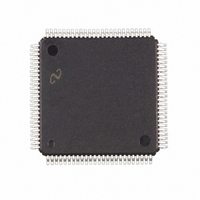
FPD85310VJD National Semiconductor, FPD85310VJD Datasheet - Page 13

FPD85310VJD
Manufacturer Part Number
FPD85310VJD
Description
IC CTRLR PANEL TIMING 100-TQFP
Manufacturer
National Semiconductor
Type
Panel Timing Controllerr
Datasheet
1.FPD85310VJD.pdf
(29 pages)
Specifications of FPD85310VJD
Voltage - Supply
3 V ~ 3.6 V
Operating Temperature
0°C ~ 70°C
Mounting Type
Surface Mount
Package / Case
100-TQFP, 100-VQFP
Lead Free Status / RoHS Status
Contains lead / RoHS non-compliant
Frequency-max
-
Output
-
Input
-
Other names
*FPD85310VJD
Available stocks
Company
Part Number
Manufacturer
Quantity
Price
Company:
Part Number:
FPD85310VJD
Manufacturer:
Texas Instruments
Quantity:
10 000
Control
Registers
Control Register
(5 bits)
0-7F
80
82,81
84,83
86,85
88,87
89
8B,8A
8D,8C
8F,8E
91,90
92
Functional Description
Address
EEPROM
Address
DDC VESA DATA
programmed to 00H for EEPROM auto detect
gpo [8]_pstart_reg (10)
gpo [8]_pcount_reg (11)
gpo [8]_lstart_reg (11)
gpo [8]_lcount_reg (11)
gpo [8]_cont_reg (5)
gpo [7]_pstart_reg (10)
gpo [7]_pcount_reg (11)
gpo [7]_lstart_reg (11)
gpo [7]_lcount_reg (11)
gpo [7]_cont_reg (5)
TABLE 2. FPD85310 Programmable Register Definition (Continued)
The control registers provide mode setting information to the input and output interfaces.
[0]. Output polarity - defines active high or active low output
[1]. Toggle circuit enable/disable
[2].
[4:3]
(Examples) GPO # -1 AND GPO # , (GPO # -2 and GPO # -1) OR GPO # and etc.
(Continued)
“0” = normal output (active high)
“1” = inverted output (active low)
“0” = Normal GPO output; Toggle circuitry disabled
“1” = Toggle circuitry enabled; output transitions after 1 clock (pixel counter) whenever
programmed rising edge of GPO occurs.
When “toggle circuit” is enable, the value of “Horizontal Duration” register programming
determine; “001h” ’1 H-line-1’ = 1 H-line toggling, ’1 H-line’ ’2 H-line-1’ = 2 H-line
toggling, etc. up to 11 bits are set.
Automatic Frame Size Detection
GPO [0:1]
“0” = Normal Operation
“1” = Used with toggle circuitry to create a “continuous” REV signal. NOTE: The value
of the vertical duration register is overwritten.
GPO [2:8]
“0” = Normal Operation
“1” = Early Start capability (Vertical Duration = “00” is N/A, See Table 5 )
The value in the Vertical Start Register is subtracted from the total number of
lines/frame (auto-detected) to determine the Vertical Start position.
(It needs a full frame after RSTZ, then started with 1 frame delayed to compare to the
other GPOs)
GPO [0:8] Combination Select
“00” = Select GPO# as programmed. (no combination function)
“01” = Select GPO# “ANDed” with GPO#-1
“10” = Select GPO# “ORed” with GPO#-1
“11” = Select GPO# and GPO#-1 on alternating frames
(
and GPO0 cannot be programmed by non-existing of “GPO-1”)
*
If the transition of GPO # -1 effect the combined result, it should be delayed 1 OCLK,
TABLE 3. EEPROM Memory Map
Data (# bits)
13
*
(Two GPOs or multi GPOs)
(HEX)
00
00,01
02,2D
00,01
03,02
00
00,14
01,E0
00,02
03,00
01
Default Values
www.national.com


