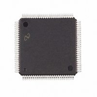
FPD85310VJD National Semiconductor, FPD85310VJD Datasheet - Page 10

FPD85310VJD
Manufacturer Part Number
FPD85310VJD
Description
IC CTRLR PANEL TIMING 100-TQFP
Manufacturer
National Semiconductor
Type
Panel Timing Controllerr
Datasheet
1.FPD85310VJD.pdf
(29 pages)
Specifications of FPD85310VJD
Voltage - Supply
3 V ~ 3.6 V
Operating Temperature
0°C ~ 70°C
Mounting Type
Surface Mount
Package / Case
100-TQFP, 100-VQFP
Lead Free Status / RoHS Status
Contains lead / RoHS non-compliant
Frequency-max
-
Output
-
Input
-
Other names
*FPD85310VJD
Available stocks
Company
Part Number
Manufacturer
Quantity
Price
Company:
Part Number:
FPD85310VJD
Manufacturer:
Texas Instruments
Quantity:
10 000
www.national.com
Control
Registers
Output Format
Control
Functional Description
PROGRAMMABLE REGISTERS
At power-up, data is read from an external EEPROM. If any-
thing other than 00H is read back on the first EEPROM ac-
cess (indicating EEPROM not present), the internal default
EEPROM
Address
D2
D3
The control registers provide mode setting information to the input and output interfaces.
[1:0]
[2]
[3]
[4]
[5]
[6]
[7]
[1:0]
[3:2]
[7:4]
TABLE 2. FPD85310 Programmable Register Definition
(Continued)
“00” = Dual Bus, Single port CD interface
“01” = Dual Bus, Dual port CD interface
“10” = Single Bus, Single port CD interface
“11” = Not implemented (defaults to “10”)
“0” = Non-Skewed outputs
“1” = Skewed outputs
“0” = Data inversion is disabled
“1” = Data inversion is enabled
“0” = Data inversion when GPO[0] is “0”
“1” = Data inversion when GPO[0] is “1”
“0” = Even and Odd data inversion when data inversion is enabled
“1” = Odd data inversion determined by bit[4], Even data opposite of Odd data
“0” = Polarity Function disabled
“1” = Polarity Function enabled
“0” = OPOL/EPOL = 0 when data is inverted
“1” = OPOL/EPOL = 1 when data is inverted
Odd Start Pulse Offset
“00” = Start pulse 0 clocks before data
“01” = Start pulse 1 clock before data
“10” = Start pulse 2 clocks before data
“11” = Start pulse 3 clocks before data
Even Start Pulse Offset
“00” = Start pulse 0 clocks before data
“01” = Start pulse 1 clock before data
“10” = Start pulse 2 clocks before data
“11” = Start pulse 3 clocks before data
Unused Pixels
“0000” = no unconnected pixels at beginning of first CD
“0001” = 1 unconnected pixel at beginning of first CD
“0010” = 2 unconnected pixels at beginning of first CD
“1111” = 15 unconnected pixels at beginning of first CD
...
...
10
values are used. The following parameters are initialized at
power up. Pullups must be used on EE_SD and EE_SC
pins.


