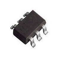
BGM1012 T/R NXP Semiconductors, BGM1012 T/R Datasheet - Page 4

BGM1012 T/R
Manufacturer Part Number
BGM1012 T/R
Description
RF Amplifier TAPE-7 MMIC-RFSS
Manufacturer
NXP Semiconductors
Type
General Purpose Wideband Amplifierr
Datasheet
1.BGM1012115.pdf
(13 pages)
Specifications of BGM1012 T/R
Operating Frequency
1 GHz
Noise Figure
4.8 dB
Bandwidth
3600 MHz
Operating Supply Voltage
3 V
Supply Current
14.6 mA
Maximum Power Dissipation
200 mW
Maximum Operating Temperature
+ 150 C
Mounting Style
SMD/SMT
Package / Case
SOT-363
Number Of Channels
1 Channel
Lead Free Status / RoHS Status
Lead free / RoHS Compliant
Other names
BGM1012,115
NXP Semiconductors
CHARACTERISTICS
V
2002 Sep 06
I
s
R
R
s
NF
BW
K
P
P
IP3
IP3
S
S
SYMBOL
L(sat)
L 1 dB
MMIC wideband amplifier
L IN
L OUT
21
12
= 3 V; I
(in)
(out)
2
2
S
= 14.6 mA; T
supply current
insertion power gain
return losses input
return losses output
isolation
noise figure
bandwidth
stability factor
saturated load power
load power
input intercept point
output intercept point
PARAMETER
j
= 25 C; unless otherwise specified.
f = 100 MHz
f = 1 GHz
f = 1.8 GHz
f = 2.2 GHz
f = 2.6 GHz
f = 3 GHz
f = 1 GHz
f = 2.2 GHz
f = 1 GHz
f = 2.2 GHz
f = 1 GHz
f = 2.2 GHz
f = 1 GHz
f = 2.2 GHz
at s
f = 1 GHz
f = 2.2 GHz
f = 1 GHz
f = 2.2 GHz
at 1 dB gain compression; f = 1 GHz
at 1 dB gain compression; f = 2.2 GHz
f = 1 GHz
f = 2.2 GHz
f = 1 GHz
f = 2.2 GHz
21
2
3 dB below flat gain at 1 GHz 3.1
CONDITIONS
4
11
19
19
19
19
18
16
9
13
11
10
30
35
1.5
3
8
3.5
4
1.5
4
9
16
11
MIN.
14.6
19.5
20.1
20.4
20.4
19.9
18.7
11
15
14
13
33
38
4.8
4.9
3.6
2.1
3.4
9.7
5.6
6.0
3.4
2
7
18
13
TYP.
Product specification
20
5.3
19
21
21
22
21
20
5.1
BGM1012
MAX.
mA
dB
dB
dB
dB
dB
dB
dB
dB
dB
dB
dB
dB
dB
dB
GHz
dBm
dBm
dBm
dBm
dBm
dBm
dBm
dBm
UNIT


