BFP 540 E6327 Infineon Technologies, BFP 540 E6327 Datasheet
BFP 540 E6327
Specifications of BFP 540 E6327
BFP540E6327INTR
BFP540E6327XT
SP000012602


Related parts for BFP 540 E6327


BFP 540 E6327 Summary of contents
Page 1
NPN Silicon RF Transistor • For highest gain low noise amplifier at 1.8 GHz • Outstanding Noise Figure F = 0.9 dB • Gold metallization for high reliability • SIEGET 45 - Line • ...
Page 2
Thermal Resistance Parameter 1) Junction - soldering point Electrical Characteristics at T Parameter DC Characteristics Collector-emitter breakdown voltage mA Collector-emitter cutoff current Collector-base ...
Page 3
Electrical Characteristics at T Parameter AC Characteristics (verified by random sampling) Transition frequency mA GHz C CE Collector-base capacitance MHz ...
Page 4
Simulation Data For SPICE-model as well as for S-parameters including noise parameters refer to our internet website: www.infineon.com/rf.models. and download the latest version before actually starting your design. The simulation data have been generated and verified GHz ...
Page 5
Total power dissipation P tot 300 mW 200 150 100 Permissible Pulse Load ƒ totmax totDC 0.005 0.01 0.02 0.05 0.1 0.2 ...
Page 6
Third order Intercept Point IP =50 Ω ) (Output parameter 1.8GHz CE 30 dBm ...
Page 7
Power gain 20mA Parameter in GHz 0.5 1 1.5 2 2.5 Noise figure ...
Page 8
Source impedance for min. noise figure vs. frequency 5mA / 20mA CE C +j50 +j25 +j10 1.8GHz 2.4GHz 3GHz 100 4GHz 5mA 5GHz -j10 20mA 6GHz -j25 -j50 +j100 0.9GHz -j100 ...
Page 9
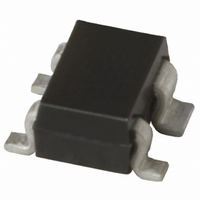
Package Outline +0.1 0.3 -0.05 4x 0.1 M Foot Print Marking Layout (Example) Standard Packing Reel ø180 mm = 3.000 Pieces/Reel Reel ø330 mm = 10.000 Pieces/Reel Pin 1 Package SOT343 0.9 ±0.1 2 ±0.2 0.1 MAX. 1.3 0.1 4 ...
Page 10
... For information on the types in question, please contact the nearest Infineon Technologies Office. Infineon Technologies components may be used in life-support devices or systems only with the express written approval of Infineon Technologies failure of such components can reasonably be expected to cause the failure of that life-support device or system or to affect the safety or effectiveness of that device or system. ...