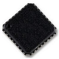
AD5748ACPZ Analog Devices Inc, AD5748ACPZ Datasheet - Page 29

AD5748ACPZ
Manufacturer Part Number
AD5748ACPZ
Description
ZDPLC +/-24V DRIVER
Manufacturer
Analog Devices Inc
Datasheet
1.AD5748ACPZ-RL7.pdf
(32 pages)
Specifications of AD5748ACPZ
Amplifier Type
Instrumentation
Number Of Circuits
1
Slew Rate
2 V/µs
Current - Output / Channel
15mA
Voltage - Supply, Single/dual (±)
±12 V ~ 24 V
Operating Temperature
-40°C ~ 105°C
Mounting Type
Surface Mount
Package / Case
*
No. Of Amplifiers
3
Supply Voltage Range
± 12V To ± 24V
Supply Current
5.2mA
Amplifier Case Style
LFCSP
No. Of Pins
32
Operating Temperature Range
-40°C To +105°C
Svhc
No
Rohs Compliant
Yes
Bandwidth
100kHz
Amplifier Output
Differential
Lead Free Status / RoHS Status
Lead free / RoHS Compliant
Output Type
-
Gain Bandwidth Product
-
-3db Bandwidth
-
Current - Input Bias
-
Voltage - Input Offset
-
Current - Supply
-
Lead Free Status / RoHS Status
Lead free / RoHS Compliant
CURRENT SETTING RESISTOR
Referring to Figure 1, R
the voltage-to-current conversion circuitry. The nominal value
of the internal current sense resistor is 15 kΩ. To allow for over-
range capability in current mode, the user can also select the
internal current sense resistor to be 14.7 kΩ, giving a nominal
2% overrange capability. This feature is available in the 0 mA
to 21 mA and 4 mA to 21 mA current ranges.
The stability of the output current value over temperature is
dependent on the stability of the value of R
improving the stability of the output current over temperature,
an external low drift resistor can be connected to the REXT1
and REXT2 pins of the AD5748, which can be used instead of
the internal resistor. The external resistor is selected via the
input shift register. If the external resistor option is not used,
the REXT1 and REXT2 pins should be left floating.
SET
is an internal sense resistor as part of
SET
. As a method of
Rev. A | Page 29 of 32
PACKET ERROR CHECKING
To verify that data has been received correctly in noisy environ-
ments, the AD5748 offers the option of error checking based on
an 8-bit (CRC-8) cyclic redundancy check. The device controlling
the AD5748 should generate an 8-bit frame check sequence
using the following polynomial:
This is added to the end of the data-word, and 24 data bits are
sent to the AD5748 before taking SYNC high. If the AD5748
receives a 24-bit data frame, it performs the error check when
SYNC goes high. If the check is valid, then the data is written
to the selected register. If the error check fails, the FAULT pin
goes low and Bit D3 of the status register is set. After reading
this register, this error flag is cleared automatically and the
FAULT pin goes high again.
FAULT
SYNC
SCLK
SYNC
SCLK
SDIN
SDIN
C(x) = x
(MSB)
(MSB)
D15
D23
16-BIT DATA TRANSER WITH ERROR CHECKING
16-BIT DATA TRANSER—NO ERROR CHECKING
8
+ x
Figure 53. PEC Error Checking Timing
2
+ x
UPDATE ON SYNC HIGH
16-BIT DATA
16-BIT DATA
1
+ 1
ONLY IF ERROR CHECK PASSED
UPDATE AFTER SYNC HIGH
(LSB)
(LSB)
D0
D8
ERROR CHECK FAILS
FAULT GOES LOW IF
D7
8-BIT FCS
AD5748
D0


