DLP-USB245M DLP Design Inc, DLP-USB245M Datasheet - Page 5
DLP-USB245M
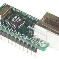
Manufacturer Part Number
DLP-USB245M
Description
Interface Modules & Development Tools USB-FIFO Adapter
Manufacturer
DLP Design Inc
Datasheet
1.DLP-USB245M-G.pdf
(15 pages)
Specifications of DLP-USB245M
Interface Type
USB
Operating Supply Voltage
- 0.5 V to + 6 V
Product
Interface Modules
For Use With/related Products
FT245BM
Lead Free Status / RoHS Status
Lead free / RoHS Compliant


5. Run the serializer program and write the VID (0403), PID (6001), a description string of your choosing and
NOTE 1 - The DLP-USB245M comes pre-programmed with a default VID and PID. Step 5 is optional and only
required if different VID/PID codes are required.
NOTE 2 – The “Test” button on the serializer program is intended for use with the DLP-USB232M module (and
At this point the DLP-USB245M is ready for use. Note that the DLP-USB245M will appear non-responsive if data sent
from the host PC is not read from the FT245BM device by an attached microcontroller/microprocessor/DSP/FPGA/
etc…
in step one. Windows will then complete the installation of the device drivers for the DLP-USB245M board. The
next time the DLP-USB245M module is attached, the host PC will immediately load the correct drivers without any
prompting. Reboot the PC if prompted to do so.
manufacturers ID as instructed in the instruction manual that was downloaded with the serializer software.
Terminate the serializer program and disconnect the DLP-USB245M board from the USB cable. Wait 10 seconds
and reconnect the DLP-USB245M board. Reboot the PC if instructed to do so.
FT232BM device) and will fail if used with the DLP-USB245M module. The “Read” function will work and will
present the contents of the EEPROM as well as the serial number and description strings stored in the EEPROM.
Copyright © DLP Design 2002
DLP-USB245M User Manual
Page 5 of 15
Related parts for DLP-USB245M
Image
Part Number
Description
Manufacturer
Datasheet
Request
R

Part Number:
Description:
Interface Modules & Development Tools USB to MSP430 w/ FTDI FT2232H
Manufacturer:
DLP Design Inc
Datasheet:

Part Number:
Description:
MODULE USB SECURITY DONGLE
Manufacturer:
DLP Design Inc
Datasheet:

Part Number:
Description:
MODULE USB-TO-UART/FIFO HS 18DIP
Manufacturer:
DLP Design Inc
Datasheet:

Part Number:
Description:
MODULE USB ADAPTER FOR FT2232D
Manufacturer:
DLP Design Inc
Datasheet:

Part Number:
Description:
MODULE USB-TO-FPGA TOOL W/MANUAL
Manufacturer:
DLP Design Inc
Datasheet:
Part Number:
Description:
Interface Modules & Development Tools RETRACTABLE USB CBL USB TO MINI USB
Manufacturer:
DLP Design Inc
Part Number:
Description:
Interface Modules & Development Tools USB FPGA Module w/ Xilinx XC3S400A
Manufacturer:
DLP Design Inc
Datasheet:

Part Number:
Description:
MODULE USB-TO-PARL FIFO 18-DIP
Manufacturer:
DLP Design Inc
Datasheet:

Part Number:
Description:
MODULE USB-TO-SRL UART 18-DIP
Manufacturer:
DLP Design Inc
Datasheet:

Part Number:
Description:
MODULE USB ADAPTR FOR FT2232D LP
Manufacturer:
DLP Design Inc
Datasheet:

Part Number:
Description:
MODULE USB-MCU FT245RL W/16F877A
Manufacturer:
DLP Design Inc
Datasheet:

Part Number:
Description:
MODULE USB-TO-FPGA TRAINING TOOL
Manufacturer:
DLP Design Inc
Datasheet:

Part Number:
Description:
MODULE USB-MCU FT232R W/18F2410
Manufacturer:
DLP Design Inc
Datasheet:

Part Number:
Description:
MODULE USB-MCU FT245RL W/SX48
Manufacturer:
DLP Design Inc
Datasheet:

Part Number:
Description:
MODULE USB-MCU FT2232D W/16F877A
Manufacturer:
DLP Design Inc
Datasheet: