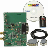
EVAL-ADF4360-7EBZ1 Analog Devices Inc, EVAL-ADF4360-7EBZ1 Datasheet - Page 21

EVAL-ADF4360-7EBZ1
Manufacturer Part Number
EVAL-ADF4360-7EBZ1
Description
PLL/Frequency Synthesizer EVAL BOARD
Manufacturer
Analog Devices Inc
Datasheet
1.ADF4360-7BCPZ.pdf
(28 pages)
Specifications of EVAL-ADF4360-7EBZ1
Silicon Manufacturer
Analog Devices
Application Sub Type
Integer-N Synthesizer
Kit Application Type
Clock & Timing
Silicon Core Number
ADF4360-7
Kit Contents
Board
Main Purpose
Timing, Frequency Synthesizer
Embedded
No
Utilized Ic / Part
ADF4360-7
Primary Attributes
Single Integer-N PLL with VCO
Secondary Attributes
900MHz, 200kHz PFD
Frequency
1.8GHz
Rohs Compliant
Yes
Lead Free Status / RoHS Status
Lead free / RoHS Compliant
Other names
EVAL-ADF4360-7EB1
EVAL-ADF4360-7EB1
Q5173330
Q5652985
EVAL-ADF4360-7EB1
Q5173330
Q5652985
APPLICATIONS
FREQUENCY GENERATOR
The wide frequency range of the AD4360-7, plus the on-chip
divider, make it an ideal choice for implementing any general
purpose clock generator or LO.
To implement a clock generator in the FM band, it is necessary
to use an external divider. The ADF4007 contains a hardware-
programmable N divider, allowing division ratios of 8, 16, 32,
and 64. This divided-down signal is accessed from the
MUXOUT pin of the ADF4007.
The minimum frequency that can be fed to the ADF4007 is
500 MHz. Therefore, 2.2 nH inductors were used to set the
fundamental frequency of oscillation at 1 GHz, with a range
from 950 MHz to 1100 MHz.
FREF
IN
1nF
10µF
1nF
4.7kΩ
1nF
51Ω
14
16
17
18
19
12
13
CPGND
C
REF
CLK
DATA
LE
C
R
1
V
V
N
C
SET
VCO
VCO
6
IN
3
DV
8
21
DD
AGND DGND
11 22 15
ADF4360-7
AV
V
DD
2
DD
CE MUXOUT
23
DETECT
L1 L2 RF
LOCK
9
20
2.2nH
10
2.2nH
RF
V
OUT
OUT
TUNE
CP
A
B
24
7
4
5
V
470pF
Figure 23. Frequency Generator
VCO
51Ω
Rev. A | Page 21 of 28
6.2kΩ
6.8nF
51Ω
13kΩ
100pF
100pF
220pF
4.7kΩ
This allows frequencies as low as 8 MHz and as high as
137 MHz to be generated using a single system. In the circuit
drawn in Figure 23, the ADF4360-7 is being used to generate
1024 MHz, and the ADF4007 is being used to divide by 8. To
provide a channel spacing of 100 kHz, a PFD frequency of
800 kHz is used for the ADF4360-7 PLL. The loop bandwidth
is chosen to be 20 kHz.
The output range of the system in Figure 23 is approximately
120 MHz to 135 MHz. The output phase noise is −104 dBc/Hz
at 1 kHz offset. Using different inductor values allows the
ADF4360-7 to be used to synthesize any different range of
frequencies over the operation of the part (235 MHz to
1800 MHz).
REF
RF
RF
IN
IN
CPGND
IN
R
A
B
SET
CHARGE
R COUNTER
PUMP
GND
÷2
CP
FREQUENCY
DETECTOR
PHASE
ADF4007
VP
N COUNTER
N1
V
VDD
÷32, ÷64
÷8, ÷16,
DD
M2
N2
MUX
ADF4360-7
M1
MUXOUT
TO LO
PORT


