EVAL-ADF4360-7EBZ1 Analog Devices Inc, EVAL-ADF4360-7EBZ1 Datasheet - Page 18
EVAL-ADF4360-7EBZ1
Manufacturer Part Number
EVAL-ADF4360-7EBZ1
Description
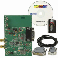
PLL/Frequency Synthesizer EVAL BOARD
Manufacturer
Analog Devices Inc
Datasheet
1.ADF4360-7BCPZ.pdf
(28 pages)
Specifications of EVAL-ADF4360-7EBZ1
Silicon Manufacturer
Analog Devices
Application Sub Type
Integer-N Synthesizer
Kit Application Type
Clock & Timing
Silicon Core Number
ADF4360-7
Kit Contents
Board
Main Purpose
Timing, Frequency Synthesizer
Embedded
No
Utilized Ic / Part
ADF4360-7
Primary Attributes
Single Integer-N PLL with VCO
Secondary Attributes
900MHz, 200kHz PFD
Frequency
1.8GHz
Rohs Compliant
Yes
Lead Free Status / RoHS Status
Lead free / RoHS Compliant
Other names
EVAL-ADF4360-7EB1
EVAL-ADF4360-7EB1
Q5173330
Q5652985
EVAL-ADF4360-7EB1
Q5173330
Q5652985


ADF4360-7
Hardware Power-Up/Power-Down
If the part is powered down via the hardware (using the CE pin)
and powered up again without any change to the N counter
register during power-down, the part locks at the correct fre-
quency, because the part is already in the correct frequency
band. The lock time depends on the value of capacitance on the
C
capacitance of 440 nF on this pin enables lock times of <600 µs.
The N counter value cannot be changed while the part is in
power-down, since the part may not lock to the correct
frequency on power-up. If it is updated, the correct program-
ming sequence for the part after power-up is the R counter
latch, followed by the control latch, and finally the N counter
latch, with the required interval between the control latch and N
counter latch, as described in the Initial Power-Up section.
N
pin, which is <10 ms for 10 µF capacitance. The smaller
Rev. A | Page 18 of 28
Software Power-Up/Power-Down
If the part is powered down via the software (using the control
latch) and powered up again without any change to the N
counter latch during power-down, the part locks at the correct
frequency, because the part is already in the correct frequency
band. The lock time depends on the value of capacitance on the
C
capacitance of 440 nF on this pin enables lock times of <600 µs.
The N counter value cannot be changed while the part is in
power-down, because the part may not lock to the correct
frequency on power-up. If it is updated, the correct program-
ming sequence for the part after power-up is to the R counter
latch, followed by the control latch, and finally the N counter
latch, with the required interval between the control latch and N
counter latch, as described in the Initial Power-Up section.
N
pin, which is <10 ms for 10 µF capacitance. The smaller
Related parts for EVAL-ADF4360-7EBZ1
Image
Part Number
Description
Manufacturer
Datasheet
Request
R

Part Number:
Description:
±1.7g Dual-Axis IMEMS Accelerometer Evaluation Board
Manufacturer:
Analog Devices Inc
Datasheet:

Part Number:
Description:
Inertial Sensor Evaluation System
Manufacturer:
Analog Devices Inc
Datasheet:
Part Number:
Description:
Manufacturer:
Analog Devices Inc
Datasheet:
Part Number:
Description:
Manufacturer:
Analog Devices Inc
Datasheet:
Part Number:
Description:
Manufacturer:
Analog Devices Inc
Datasheet:
Part Number:
Description:
Manufacturer:
Analog Devices Inc
Datasheet:
Part Number:
Description:
Manufacturer:
Analog Devices Inc
Datasheet:
Part Number:
Description:
Manufacturer:
Analog Devices Inc
Datasheet:
Part Number:
Description:
Manufacturer:
Analog Devices Inc
Datasheet:
Part Number:
Description:
Manufacturer:
Analog Devices Inc
Datasheet:
Part Number:
Description:
Manufacturer:
Analog Devices Inc
Datasheet:
Part Number:
Description:
Manufacturer:
Analog Devices Inc
Datasheet:
Part Number:
Description:
Manufacturer:
Analog Devices Inc
Datasheet: