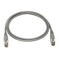
11730D AGILENT TECHNOLOGIES, 11730D Datasheet - Page 64

11730D
Manufacturer Part Number
11730D
Description
SENSOR CABLE, 50FT
Manufacturer
AGILENT TECHNOLOGIES
Datasheet
1.11730D.pdf
(234 pages)
Specifications of 11730D
Leaded Process Compatible
No
Peak Reflow Compatible (260 C)
No
Cable Length
50ft
Features
Reduces RFI Effect On Low Power Readings With Improved Shielding Design
Cable Assembly Type
Sensor
Cable Color
Gray
Rohs Compliant
No
For Use With
8480 & E-Series Power Sensors
Lead Free Status / RoHS Status
Contains lead / RoHS non-compliant
- Current page: 64 of 234
- Download datasheet (7Mb)
Open circuit voltage sensitivity
The open circuit voltage sensitivity (K)
describes the slope of the transfer function
of the detectors. This represents the
conversion of RF/microwave power to a
voltage at the output connector, typically
specified in mV/mW. The value is an
indication of the efficiency of the diode in
converting the input power to a useful
voltage.
Sensitivity is measured with the detector
terminated in a high impedance. When
used in video pulse applications, the
sensitivity will appear to be much lower
when terminated in 50 or 75 ohms for
connection to an oscilloscope. Another
factor, called the Figure of Merit, gives an
indication of low-level sensitivity without
consideration of a load circuit. It is useful
for comparing detectors with different
values of K and R v . Figure of Merit equals
K/√R v , where R v = internal video
resistance.
Tangential sensitivity
Tangential sensitivity is the lowest input
signal power level for which the detector
will have an 8 dB signal-to-noise ratio at
the output of a test video amplifier. Test
amplifier gain is not relevant because it
applies to both signal and noise. Agilent
detectors are designed for optimal flatness
and SWR. Figure 2 shows typical
tangential sensitivity.
Figure 2. Typical tangential sensitivity performance.
Figure 3. Typical output response with temperature
(Pin <–20 dBm) (Schottky diode).
Where:
Output voltage versus
temperature
For applications such as power monitoring
and leveling that require stable output
voltage versus input power, the designer
can choose a resistive termination that will
optimize the transfer function over a wide
temperature range. Figure 3 shows how
sensitivity changes over temperature with
different load resistances. In this case, a
value between 1 kΩ and 10 kΩ will be
optimum for 0 to 50 °C.
P tss (watts) =
–10
–2
–0
–2
–4
–6
–8
–80
R
L
B = Video amplifier bandwidth (Hz)
F = Video amplifier noise factor
R v = Video resistance (
K = Open circuit voltage
R
= 1 kΩ
L
–60
3.23 x 10 -10
= 10 (Noise figure/10)
Sensitivity (mV/mW)
= 10 kΩ
R
R
L
L
= 50 kΩ
= 100 Ω
–40
K
√
BFR
–20
v
Ω)
Temperature (°C)
@ 300 °K
0
www.agilent.com/find/mta
20
40
–10
–20
–30
–40
–50
–60
–70
–80
Rise time
In applications where the frequency
response of another microwave device is
being measured, or where a fast rise time
response is required for accurate
measurements, the rise time of the
detector becomes very important. It is
critical to note that the rise time is
dependent upon the characteristics of the
detector AND the test equipment.
0
10
2
60
10
T
3
a
=100 °C
80
T
10
Bandwidth (Hz)
a
Detectors (continued)
T
4
= 25 °C
a
= –60 °C
100
10
5
Detectors
10
6
10
7
10
8
53
8
Related parts for 11730D
Image
Part Number
Description
Manufacturer
Datasheet
Request
R

Part Number:
Description:
Agilent Tachyon DX4+ (HPFC-5700) Dual-Channel 4-Gb Fibre Channel Controller With The Data Integrity Field (DIF) Feature
Manufacturer:
Agilent Technologies, Inc.

Part Number:
Description:
Manufacturer:
Agilent Technologies, Inc.
Datasheet:

Part Number:
Description:
Manufacturer:
Agilent Technologies, Inc.
Datasheet:

Part Number:
Description:
Manufacturer:
Agilent Technologies, Inc.
Datasheet:

Part Number:
Description:
Manufacturer:
Agilent Technologies, Inc.
Datasheet:

Part Number:
Description:
Manufacturer:
Agilent Technologies, Inc.
Datasheet:

Part Number:
Description:
Manufacturer:
Agilent Technologies, Inc.
Datasheet:

Part Number:
Description:
Manufacturer:
Agilent Technologies, Inc.
Datasheet:

Part Number:
Description:
Manufacturer:
Agilent Technologies, Inc.
Datasheet:

Part Number:
Description:
Manufacturer:
Agilent Technologies, Inc.
Datasheet:

Part Number:
Description:
Manufacturer:
Agilent Technologies, Inc.
Datasheet:

Part Number:
Description:
Manufacturer:
Agilent Technologies, Inc.
Datasheet:

Part Number:
Description:
1.0625 GBd Fibre Channel 10x10 mm QFP Transceiver Chip (Recommend HDMP-1636A for new designs)
Manufacturer:
Agilent Technologies, Inc.
Datasheet:

Part Number:
Description:
Manufacturer:
Agilent Technologies, Inc.
Datasheet:

Part Number:
Description:
1.0625-2.125 GBd Serdes Circuits: SSTL_2
Manufacturer:
Agilent Technologies, Inc.
Datasheet:


