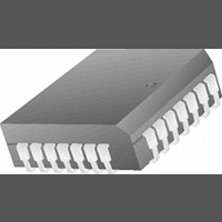
CS5102A-BL Cirrus Logic Inc, CS5102A-BL Datasheet - Page 7

CS5102A-BL
Manufacturer Part Number
CS5102A-BL
Description
A/D Converter (A-D) IC
Manufacturer
Cirrus Logic Inc
Specifications of CS5102A-BL
Input Channels Per Adc
2
Mounting Type
Surface Mount
No. Of Channels
2
Power Rating
44mW
Supply Voltage Min
4.5V
Peak Reflow Compatible (260 C)
No
Sample Rate
20kSPS
Supply Voltage Max
5.5V
Lead Free Status / RoHS Status
Contains lead / RoHS non-compliant
Available stocks
Company
Part Number
Manufacturer
Quantity
Price
Part Number:
CS5102A-BL
Manufacturer:
CRYSTAL
Quantity:
20 000
Company:
Part Number:
CS5102A-BLZ
Manufacturer:
Cirrus Logic Inc
Quantity:
10 000
Part Number:
CS5102A-BLZ
Manufacturer:
CRYSTAL
Quantity:
20 000
SWITCHING CHARACTERISTICS
Note: 24. Minimum CLKIN period is 0.625 s in FRN mode (20 kHz sample rate). At temperatures >+85 C,
DS45F2
CLKIN Period
CLKIN Low Time
CLKIN High Time
Crystal Frequency
SLEEP Rising to Oscillator Stable
RST Pulse Width
RST to STBY Falling
RST Rising to STBY Rising
CH1/2 Edge to TRK1, TRK2 Rising
CH1/2 Edge to TRK1, TRK2 Falling
HOLD to SSH Falling
HOLD to TRK1, TRK2, Falling
HOLD to TRK1, TRK2, SSH Rising
HOLD Pulse Width
HOLD to CH1/2 Edge
HOLD Falling to CLKIN Falling
VA+, VD+ = 5V
25. External loading capacitors are required to allow the crystal to oscillate. Maximum crystal frequency
26. With a 2.0 MHz crystal, two 33 pF loading capacitors and a 10 M
27. These times are for FRN mode.
28. SSH only works correctly if HOLD falling edge is within +15 to +30 ns of CH1/2 edge or if CH1/2 edge
29. When HOLD goes low, the analog sample is captured immediately. To start conversion, HOLD must
and with clock frequencies <1.6 MHz, analog performance may be degraded.
is 1.6 MHz in FRN mode (20 kHz sample rate).
occurs after HOLD rises to 64 t
be latched by a falling edge of CLKIN. Conversion will begin on the next rising edge of CLKIN
after HOLD is latched. If HOLD is operated synchronous to CLKIN, the HOLD pulse width may be as
narrow as 150 ns for all CLKIN frequencies if CLKIN falls 55 ns after HOLD falls. This
ensures that the HOLD pulse will meet the minimum specification for t
10%; VA-, VD- = -5V
Parameter
clk
10%; Inputs: Logic 0 = 0V, Logic 1 = VD+; C
after HOLD has fallen. These times are for PDT and RBT modes.
(Note 24, 25)
(Note 18,24)
(T
(Note 26)
(Note 27)
(Note 27)
(Note 28)
(Note 28)
(Note 28)
(Note 29)
(Note 28)
(Note 29)
A
= T
MIN
to T
Symbol
t
t
t
t
t
t
t
t
t
drsh1
dfsh4
dfsh2
dfsh1
f
t
t
drsh
t
t
hold
dhlri
clkh
t
drrs
MAX
xtal
clkl
cal
hcf
clk
rst
-
;
1t
66t
clk
Min
200
200
150
0.5
0.9
15
55
-
-
-
-
-
-
-
+20
clk
parallel resistor (see Figure 8).
hcf
2,882,040
.
Typ
100
120
1.6
20
80
60
-
-
-
-
-
-
-
-
-
L
= 50 pF)
68t
68t
CS5102A
1tclk+10
63t
64t
Max
clk
clk
2.0
10
-
-
-
-
-
-
-
-
+260
+260
clk
clk
Units
MHz
ms
t
ns
ns
ns
ns
ns
ns
ns
ns
ns
ns
ns
ns
clk
s
7


