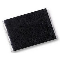
H27UF081G1M-TPCB HYNIX SEMICONDUCTOR, H27UF081G1M-TPCB Datasheet - Page 11

H27UF081G1M-TPCB
Manufacturer Part Number
H27UF081G1M-TPCB
Description
IC, MEMORY, FLASH NAND 1GB, TSOP48
Manufacturer
HYNIX SEMICONDUCTOR
Datasheet
1.H27UF081G1M-TPCB.pdf
(39 pages)
Specifications of H27UF081G1M-TPCB
Access Time
45ns
Supply Voltage Range
2.7V To 3.6V
Memory Case Style
TSOP
No. Of Pins
48
Operating Temperature Range
0°C To +70°C
Base Number
27
Interface
Serial
Logic
RoHS Compliant
Package / Case
TSOP
Memory Type
Flash - NAND
Memory Configuration
128M X 8
Rohs Compliant
Yes
Memory Size
1Gbit
Preliminary
HY27US(08/16)1G1M Series
1Gbit (128Mx8bit / 64Mx16bit) NAND Flash
3. DEVICE OPERATION
3.1 Page Read.
Upon initial device power up, the device defaults to Read1 mode. This operation is also initiated by writing 00h to the
command register along with followed by the four address input cycles. Once the command is latched, it does not
need to be written for the following page read operation.
Three types of operations are available: random read, serial page read and sequential row read.
The random read mode is enabled when the page address is changed. The 528 bytes (x8 device) or 264 word (x16
device) of data within the selected page are transferred to the data registers in less than access random read time tR
(15us). The system controller can detect the completion of this data transfer tR (15us) by analyzing the output of R/B
pin. Once the data in a page is loaded into the registers, they may be read out in 50ns cycle time by sequentially puls-
ing RE. High to low transitions of the RE clock output the data stating from the selected column address up to the last
column address.
After the data of last column address is clocked out, the next page is automatically selected for sequential row read.
Waiting tR again allows reading the selected page. The sequential row read operation is terminated by bringing CE
high.
The way the Read1 and Read2 commands work is like a pointer set to either the main area or the spare area. Writing
the Read2 command user may selectively access the spare area of bytes 512 to 527. Addresses A0 to A3 set the start-
ing address of the spare area while addresses A4 to A7 are ignored. Unless the operation is aborted, the page address
is automatically incremented for sequential row
Read as in Read1 operation and spare sixteen bytes of each page may be sequentially read. The Read1 command
(00h/01h) is needed to move the pointer back to the main area. Figure_10 to 12 show typical sequence and timings
for each read operation.
Devices with automatic read of page0 at power up can be provided on request.
3.2 Page Program.
The device is programmed basically on a page basis, but it does allow multiple partial page programming of a byte or
consecutive bytes up to 528 (x8 device), in a single page program cycle.
The number of consecutive partial page programming operation within the same page without an intervening erase
operation must not exceed 8; for example, 4 times for main array (X8 device:1time/512byte, X16 device:1time
256word) and 4 times for spare array (X8 device:1time/16byte ,X16 device:1time/8word).
The addressing may be done in any random order in a block. A page program cycle consists of a serial data loading
period in which up to 528 bytes (x8 device) or 264 word (x16 device) of data may be loaded into the page register, fol-
lowed by a non-volatile programming period where the loaded data is programmed into the appropriate cell. Serial
data loading can be started from 2nd half array by moving pointer. About the pointer operation, please refer to
Figure_22.
The data-loading sequence begins by inputting the Serial Data Input command (80h), followed by the four address
input cycles and then serial data loading. The Page Program confirm command (10h) starts the programming process.
Writing 10h alone without previously entering the serial data will not initiate the programming process. The internal
Program Erase Controller automatically executes the algorithms and timings necessary for program and verify, thereby
freeing the system controller for other tasks. Once the program process starts, the Read Status Register command
may be entered, with RE and CE low, to read the status register. The system controller can detect the completion of a
program cycle by monitoring the R/B output, or the Status bit (I/O 6) of the Status Register. Only the Read Status
command and Reset command are valid while programming is in progress. When the Page Program is complete, the
Write Status Bit (I/O 0) may be checked Figure_14
The internal write verify detects only errors for "1"s that are not successfully programmed to "0"s. The command reg-
ister remains in Read Status command mode until another valid command is written to the command register.
Rev 0.2 / May. 2007
11


