NUMICRO-SDK Nuvoton Technology Corporation of America, NUMICRO-SDK Datasheet - Page 266
NUMICRO-SDK
Manufacturer Part Number
NUMICRO-SDK
Description
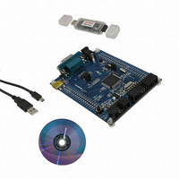
KIT EVAUATION NUC100/120/130/140
Manufacturer
Nuvoton Technology Corporation of America
Series
NuMicro™r
Type
MCUr
Datasheets
1.NUC100LC1BN.pdf
(600 pages)
2.NUMICRO-SDK.pdf
(13 pages)
3.NUMICRO-SDK.pdf
(93 pages)
4.NUMICRO-SDK.pdf
(1 pages)
Specifications of NUMICRO-SDK
Contents
Board, Cable, CD, Nu-Link
Lead Free Status / RoHS Status
Lead free / RoHS Compliant
For Use With/related Products
NUC100, NUC120, NUC130, NUC140
Available stocks
Company
Part Number
Manufacturer
Quantity
Price
Company:

Part Number:
NUMICRO-SDK
Manufacturer:
Nuvoton Technology Corporation
Quantity:
135
Company:
Part Number:
NUMICRO-SDK
Manufacturer:
NuvoTon
Quantity:
69


5.6.4.5
5.6.4.6
from bus error, STO should be set and SI should be clear to enter not addressed slave mode.
Then clear STO to release bus and to wait new communication. I
condition during this action when bus error occurs.
The data baud rate of I
not important when I
with any clock frequency up to 1MHz from master I
The data baud rate of I
If system clock = 16 MHz, the I2CLK [7:0] = 40 (28H), so data baud rate of I
+1)) = 97.5 Kbits/sec. The block diagram is showed as Figure 5-25.
There is a 14-bit time-out counter which can be used to deal with the I
out counter is enabled, the counter starts up counting until it overflows (TIF=1) and generates I
interrupt to CPU or stops counting by clearing ENTI to 0. When time-out counter is enabled,
setting flag SI to high will reset counter and re-start up counting after SI is cleared. If I
hangs up, it causes the I2CSTATUS and flag SI are not updated for a period, the 14-bit time-out
counter may overflow and acknowledge CPU the I
bit time-out counter. User may write 1 to clear TIF to zero.
I
The I
2
C Clock Baud Rate Bits (I2CLK)
2
C Time-out Counter Register (I2CTOC)
NuMicro™ NUC100 Series Technical Reference Manual
2
C is in a slave mode. In the slave modes, I
2
2
Figure 5-25: I
C setting is Data Baud Rate of I
C is determines by I2CLK [7:0] register when I
2
C Time-out Count Block Diagram
- 266 -
2
2
C interrupt. Refer to the Figure 5-25 for the 14-
C device.
2
C = (system clock) / (4x (I2CLK [7:0] +1)).
Publication Release Date: Dec. 22, 2010
2
C will automatically synchronize
2
C bus can not recognize stop
2
2
C is in a master mode. It is
C bus hang-up. If the time-
2
C = 16 MHz/ (4x (40
Revision V1.06
2
C bus
2
C
Related parts for NUMICRO-SDK
Image
Part Number
Description
Manufacturer
Datasheet
Request
R

Part Number:
Description:
IC MCU 32BIT 32KB FLASH 33QFN
Manufacturer:
Nuvoton Technology Corporation of America
Datasheet:
Part Number:
Description:
IC MCU 32BIT 32KB FLASH 48LQFP
Manufacturer:
Nuvoton Technology Corporation of America
Datasheet:

Part Number:
Description:
IC MCU 32BIT 32KB FLASH 48LQFP
Manufacturer:
Nuvoton Technology Corporation of America
Datasheet:

Part Number:
Description:
IC MCU 32BIT 64KB FLASH 33QFN
Manufacturer:
Nuvoton Technology Corporation of America
Datasheet:

Part Number:
Description:
IC MCU 32BIT 32KB FLASH 48LQFP
Manufacturer:
Nuvoton Technology Corporation of America
Datasheet:

Part Number:
Description:
IC MCU 32BIT 64KB FLASH 48LQFP
Manufacturer:
Nuvoton Technology Corporation of America
Datasheet:

Part Number:
Description:
IC MCU 32BIT 64KB FLASH 64LQFP
Manufacturer:
Nuvoton Technology Corporation of America
Datasheet:

Part Number:
Description:
IC MCU 32BIT 64KB FLASH 64LQFP
Manufacturer:
Nuvoton Technology Corporation of America
Datasheet:

Part Number:
Description:
IC MCU 32BIT 64KB FLASH 48LQFP
Manufacturer:
Nuvoton Technology Corporation of America
Datasheet:
Part Number:
Description:
IC MCU 32BIT 64KB FLASH 64LQFP
Manufacturer:
Nuvoton Technology Corporation of America
Datasheet:

Part Number:
Description:
IC MCU 32BIT 8KB FLASH 33QFN
Manufacturer:
Nuvoton Technology Corporation of America
Datasheet:

Part Number:
Description:
IC MCU 32BIT 8KB FLASH 48LQFP
Manufacturer:
Nuvoton Technology Corporation of America
Datasheet:
Part Number:
Description:
IC MCU 32BIT 16KB FLASH 33QFN
Manufacturer:
Nuvoton Technology Corporation of America
Datasheet:
Part Number:
Description:
IC MCU 32BIT 64KB FLASH 100LQFP
Manufacturer:
Nuvoton Technology Corporation of America
Datasheet:

Part Number:
Description:
IC MCU 32BIT 128KB FLASH 64LQFP
Manufacturer:
Nuvoton Technology Corporation of America
Datasheet: