BMR4500002/020 Ericsson Power Modules, BMR4500002/020 Datasheet - Page 24
BMR4500002/020
Manufacturer Part Number
BMR4500002/020
Description
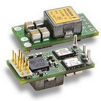
DC/DC Converters & Regulators 66W 4.5-14V OUT 20A 25.65x12.9x8.22 mm
Manufacturer
Ericsson Power Modules
Series
BMR 450r
Datasheet
1.BMR4500002020.pdf
(31 pages)
Specifications of BMR4500002/020
Output Power
110 W
Input Voltage Range
4.5 V to 14 V
Number Of Outputs
1
Output Voltage (channel 1)
0.6 V to 5.5 V
Output Current (channel 1)
20 A
Package / Case Size
25.65 mm x 12.9 mm x 8.2 mm
Output Voltage
0.6 V to 5.5 V
Product
Non-Isolated / POL
Lead Free Status / RoHS Status
Lead free / RoHS Compliant


PMBus Interface
The regulator provides a digital PMBus interface that enables
the user to monitor the input and output parameters. The
PMBus interface can also be used for configuration of the
regulator. The products can be used with any standard 2-wire
I
with PMBus version 1.1 and includes an SALERT line to help
mitigate bandwidth limitations related to continuous fault
monitoring. The PMBus signals, SCL, SDA, SALERT requires
passive pull-up resistors as stated in the SMBus Specification.
Monitoring via PMBus
A system controller can monitor a wide variety of different
parameters through the PMBus interface. The controller can
monitor for fault condition by monitoring the SALERT pin,
which will be asserted when any number of pre-configured
fault or warning conditions occur. The system controller can
also continuously monitor for any number of power conversion
parameters including but not limited to the following:
•
•
•
•
•
•
Software Tools for Design and Production
For the regulators Ericsson provides software for configuring
and monitoring via the PMBus interface for use in design and
in production.
For more information please contact your local
Ericsson sales representative.
PMBus Addressing
The PMBus address should be configured with resistors
connected between SA0 and SA1 pin to the –S pin, as shown
in the figure. Recommended resistor values for hard-wiring
PMBus addresses (series E96, 1% tolerance resistors
suggested) are shown in the table.
Schematic of connection of address resistors.
E
2
Prepared (also subject responsible if other)
EAB/FJB/GMF/EKAMAGN
Approved
EAB/FJB/GMF Torbjörn Holmberg
BMR 450 Digital PoL Regulators
Input 4.5-14 V, Output up to 20 A / 100 W
C or SMBus host device. In addition, the device is compatible
Input voltage
Output voltage
Output current
Internal junction temperature
Switching frequency
Duty cycle
SA0
SA1
−S
R SA1
R SA0
Checked
ETORHOL
The PMBus address follows the equation below:
The user can theoretically configure up to 625 unique PMBus
addresses, however the PMBus address range is inherently
limited to 128. Therefore, the user should use index values 0 -
4 on the SA1 pin and the full range of index values on the SA0
pin, which will provide 125 device address combinations. The
user shall also be aware of further limitations of the address
space as stated in the SMBus Specification.
Ericsson Confidential
PRODUCT SPECIFICATION
No.
31/1301-BMR 450 0002
Date
2010-03-02
SA0/SA1 Index
PMBus Address = 25 x (SA1 index) + (SA0 index)
10
11
12
0
1
2
3
4
5
6
7
8
9
R
Technical Specification
EN/LZT 146 400 R3A March 2010
© Ericsson AB
Rev
B
SA0
/R
12.1
13.3
14.7
16.2
17.8
19.6
21.5
23.7
26.1
28.7
31.6
10
11
SA1
[kΩ]
Reference
SA0/SA1 Index
13
14
15
16
17
18
19
20
21
22
23
24
R
SA0
/R
34.8
38.3
42.2
46.4
51.1
56.2
61.9
68.1
82.5
90.9
100
75
SA1
1 (4)
24
[kΩ]
Related parts for BMR4500002/020
Image
Part Number
Description
Manufacturer
Datasheet
Request
R

Part Number:
Description:
37.5-150W DC/DC POWER MODULES
Manufacturer:
Ericsson Power Modules
Part Number:
Description:
DC/DC Power Supply Dual-OUT 3.3V/5V 9.6A/6.4A 40W 10-Pin
Manufacturer:
Ericsson Power Modules
Part Number:
Description:
DC/DC Power Supply Single-OUT 3.3V 20A 66W 8-Pin Quarter-Brick
Manufacturer:
Ericsson Power Modules
Datasheet:
Part Number:
Description:
DC/DC Power Supply Single-OUT 1.8V 50A 90W 11-Pin
Manufacturer:
Ericsson Power Modules
Part Number:
Description:
Module DC-DC 1-OUT 1.8V 30A 54W 9-Pin
Manufacturer:
Ericsson Power Modules

Part Number:
Description:
Module DC-DC 1-OUT 1.8V 60A 108W 11-Pin Half-Brick
Manufacturer:
Ericsson Power Modules
Datasheet:

Part Number:
Description:
Module DC-DC 1-OUT 12V 25A 300W 11-Pin Half-Brick
Manufacturer:
Ericsson Power Modules
Part Number:
Description:
Module DC-DC 1-OUT 5V 20A 100W Quarter-Brick
Manufacturer:
Ericsson Power Modules

Part Number:
Description:
Module DC-DC 1-OUT 12V 6A 72W 8-Pin 1/8-Brick
Manufacturer:
Ericsson Power Modules
Datasheet:
Part Number:
Description:
Module DC-DC 1-OUT 5.05V 2A 10W 18-Pin SMD
Manufacturer:
Ericsson Power Modules
Part Number:
Description:
Manufacturer:
Ericsson Power Modules
Datasheet:

Part Number:
Description:
Module DC-DC 1-OUT 5V 60A 300W 11-Pin Half-Brick Tray
Manufacturer:
Ericsson Power Modules
Part Number:
Description:
Module DC-DC 1-OUT 12V 1A 12W 18-Pin
Manufacturer:
Ericsson Power Modules
Datasheet:
Part Number:
Description:
Module DC-DC 2-OUT 12V/-12V 0.25A 6W 18-Pin SMD
Manufacturer:
Ericsson Power Modules
Part Number:
Description:
Module DC-DC 1-OUT 28V 11A 310W 11-Pin Half-Brick Tray
Manufacturer:
Ericsson Power Modules
Datasheet: