BMR4500002/020 Ericsson Power Modules, BMR4500002/020 Datasheet - Page 18
BMR4500002/020
Manufacturer Part Number
BMR4500002/020
Description
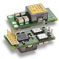
DC/DC Converters & Regulators 66W 4.5-14V OUT 20A 25.65x12.9x8.22 mm
Manufacturer
Ericsson Power Modules
Series
BMR 450r
Datasheet
1.BMR4500002020.pdf
(31 pages)
Specifications of BMR4500002/020
Output Power
110 W
Input Voltage Range
4.5 V to 14 V
Number Of Outputs
1
Output Voltage (channel 1)
0.6 V to 5.5 V
Output Current (channel 1)
20 A
Package / Case Size
25.65 mm x 12.9 mm x 8.2 mm
Output Voltage
0.6 V to 5.5 V
Product
Non-Isolated / POL
Lead Free Status / RoHS Status
Lead free / RoHS Compliant


E
EMC Specification
Conducted EMI measured according to test set-up and
standard MIL std 0141 - 58000.
The fundamental switching frequency is 320 kHz for
BMR 450.
Conducted EMI Input terminal value (typ)
EMI without filter
Test set-up
Layout Recommendations
The radiated EMI performance of the product will depend on
the PCB layout and ground layer design. It is also important to
consider the stand-off of the product. If a ground layer is used,
it should be connected to the output of the product and the
equipment ground or chassis.
A ground layer will increase the stray capacitance in the PCB
and improve the high frequency EMC performance.
Prepared (also subject responsible if other)
EAB/FJB/GMF EKAMAGN
Approved
EAB/FJB/GMF Torbjörn Holmberg
BMR 450 Digital PoL Regulators
Input 4.5-14 V, Output up to 20 A / 100 W
Checked
ETORHOL
Output Ripple and Noise
Output ripple and noise is measured with the filter according to
figure below. A 50 mm conductor works as a small inductor
forming together with the two capacitances a damped filter.
Output ripple and noise test set-up.
Operating Information
Input Voltage
The input voltage range, 4.5 - 14 V, makes the products easy
to use in intermediate bus applications when powered by a
non-regulated bus converter or a regulated bus converter.
See Ordering Information for input voltage range.
Turn-off Input Voltage Range
The product monitors the input voltage and will turn-on and
turn-off at configured levels. The default turn-on input voltage
level setting is 4.5 V, whereas the corresponding turn-off input
voltage level is 4.25 V. Hence, the default hysteresis between
turn-on and turn-off input voltage is 0.25 V. The turn-on and
turn-off levels can be reconfigured using the PMBus interface.
Please contact your local Ericsson Power Modules
representative for design support of custom configurations or
appropriate SW tools for design and down-load of new
configurations.
Remote Control
Specification version 2.0. The CTRL function allows the
product to be turned on/off by an external device like a
semiconductor or mechanical switch. By default the product
will turn on with the CTRL pin is left open and turn off when
the CTRL pin is applied to GND. The CTRL pin has an internal
pull-up resistor. The maximum required sink current is 0.5 mA.
When the CTRL pin is left open, the voltage generated on the
CTRL pin is max 6 V. The product can also be configured
using the PMBus to be “Always on”, i.e., starts immediately
Ericsson Internal
PRODUCT SPECIFICATION
No.
30/1301-BMR 450 0002 Uen
Date
2010-03-02
Vext
GND
Vout
+S
−S
CTRL
GND
Technical Specification
EN/LZT 146 400 R3A March 2010
© Ericsson AB
Rev
H
50 mm conductor
50 mm conductor
The product is equipped with a
remote control function, i.e., the
CTRL pin. The remote control can
be referenced to either the primary
negative input connection (GND) or
to an external voltage (Vext), which
is a 3 - 5 V positive supply voltage
in accordance with the SMBus
Tantalum
Capacitor
10 µF
Reference
BNC-contact to
oscilloscope
Ceramic
Capacitor
0.1 µF
1 (7)
18
Related parts for BMR4500002/020
Image
Part Number
Description
Manufacturer
Datasheet
Request
R

Part Number:
Description:
37.5-150W DC/DC POWER MODULES
Manufacturer:
Ericsson Power Modules
Part Number:
Description:
DC/DC Power Supply Dual-OUT 3.3V/5V 9.6A/6.4A 40W 10-Pin
Manufacturer:
Ericsson Power Modules
Part Number:
Description:
DC/DC Power Supply Single-OUT 3.3V 20A 66W 8-Pin Quarter-Brick
Manufacturer:
Ericsson Power Modules
Datasheet:
Part Number:
Description:
DC/DC Power Supply Single-OUT 1.8V 50A 90W 11-Pin
Manufacturer:
Ericsson Power Modules
Part Number:
Description:
Module DC-DC 1-OUT 1.8V 30A 54W 9-Pin
Manufacturer:
Ericsson Power Modules

Part Number:
Description:
Module DC-DC 1-OUT 1.8V 60A 108W 11-Pin Half-Brick
Manufacturer:
Ericsson Power Modules
Datasheet:

Part Number:
Description:
Module DC-DC 1-OUT 12V 25A 300W 11-Pin Half-Brick
Manufacturer:
Ericsson Power Modules
Part Number:
Description:
Module DC-DC 1-OUT 5V 20A 100W Quarter-Brick
Manufacturer:
Ericsson Power Modules

Part Number:
Description:
Module DC-DC 1-OUT 12V 6A 72W 8-Pin 1/8-Brick
Manufacturer:
Ericsson Power Modules
Datasheet:
Part Number:
Description:
Module DC-DC 1-OUT 5.05V 2A 10W 18-Pin SMD
Manufacturer:
Ericsson Power Modules
Part Number:
Description:
Manufacturer:
Ericsson Power Modules
Datasheet:

Part Number:
Description:
Module DC-DC 1-OUT 5V 60A 300W 11-Pin Half-Brick Tray
Manufacturer:
Ericsson Power Modules
Part Number:
Description:
Module DC-DC 1-OUT 12V 1A 12W 18-Pin
Manufacturer:
Ericsson Power Modules
Datasheet:
Part Number:
Description:
Module DC-DC 2-OUT 12V/-12V 0.25A 6W 18-Pin SMD
Manufacturer:
Ericsson Power Modules
Part Number:
Description:
Module DC-DC 1-OUT 28V 11A 310W 11-Pin Half-Brick Tray
Manufacturer:
Ericsson Power Modules
Datasheet: