BMR4500002/020 Ericsson Power Modules, BMR4500002/020 Datasheet - Page 2
BMR4500002/020
Manufacturer Part Number
BMR4500002/020
Description
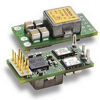
DC/DC Converters & Regulators 66W 4.5-14V OUT 20A 25.65x12.9x8.22 mm
Manufacturer
Ericsson Power Modules
Series
BMR 450r
Datasheet
1.BMR4500002020.pdf
(31 pages)
Specifications of BMR4500002/020
Output Power
110 W
Input Voltage Range
4.5 V to 14 V
Number Of Outputs
1
Output Voltage (channel 1)
0.6 V to 5.5 V
Output Current (channel 1)
20 A
Package / Case Size
25.65 mm x 12.9 mm x 8.2 mm
Output Voltage
0.6 V to 5.5 V
Product
Non-Isolated / POL
Lead Free Status / RoHS Status
Lead free / RoHS Compliant


E
Prepared (also subject responsible if other)
SEC/S Alex Luo
Approved
BMR 450 Digital PoL Regulators
Input 4.5-14 V, Output up to 20 A / 100 W
Ordering Information
Product program
BMR4500002/020
BMR4501002/020
BMR4500002/021
Product Number and Packaging
Options
Mechanical pin option
Mechanical option
Digital Interface option
Configuration file
Optional designation
n
n
n
n
Packaging
Example: Product number BMR4501002/020 equals a surface mount, open
frame, PMBus and analog voltage adjust, standard configuration variant.
For application specific configurations contact your local
Ericsson Power Modules sales representative.
General Information
Reliability
The Mean Time Between Failure (MTBF) is calculated at
full output power and an operating ambient temperature
(T
and Communication Technology (ICT) equipment. Different
methods could be used to calculate the predicted MTBF
and failure rate which may give different results. Ericsson
Power Modules currently uses Telcordia SR332.
Predicted MTBF for the series is:
-
Telcordia SR332 is a commonly used standard method
intended for reliability calculations in ICT equipment. The
parts count procedure used in this method was originally
modelled on the methods from MIL-HDBK-217F, Reliability
1
2
3
5
A
n
n
) of +40°C, which is a typical condition in Information
4
6
5 million hours according to Telcordia SR332, issue 1,
Black box technique.
n
7
BMR450 n
Description
0 = Through hole mount version (THP)
1 = Surface mount version (SMD)
0 = Open frame
02 = 4.5 – 14 Vin PMBus and analog
voltage adjust
020 = Standard configuration
021 = Application Specific Configuration
for 5.5V output voltage
Antistatic injection molded tray of 60
products (5 full trays/box = 300 products)
n
x
1
1
Output
4.5-14 V / 20 A, 100 W (TH)
4.5-14 V / 20 A, 100 W (SMD)
8.0-14 V / 18 A, 99 W (TH)
n
x
n
2
2
n
3
n
n
x
4
3
/n
5
n
n
x
6
4
n
7
/
/
/
/
/
Checked
n
x
5
n
x
6
n
x
7
Ericsson Internal
PRODUCT SPECIFICATION
No.
1/1301-BMR450 Uen
Date
2010-02-11
Predictions of Electronic Equipment. It assumes that no
reliability data is available on the actual units and devices
for which the predictions are to be made, i.e. all predictions
are based on generic reliability parameters.
Compatibility with RoHS requirements
The products are compatible with the relevant clauses and
requirements of the RoHS directive 2002/95/EC and have a
maximum concentration value of 0.1% by weight in
homogeneous materials for lead, mercury, hexavalent
chromium, PBB and PBDE and of 0.01% by weight in
homogeneous materials for cadmium.
Exemptions in the RoHS directive utilized in Ericsson
Power Modules products include:
-
-
-
Quality Statement
The products are designed and manufactured in an
industrial environment where quality systems and methods
like ISO 9000, 6σ (sigma), and SPC are intensively in use
to boost the continuous improvements strategy. Infant
mortality or early failures in the products are screened out
and they are subjected to an ATE-based final test.
Conservative design rules, design reviews and product
qualifications, plus the high competence of an engaged
work force, contribute to the high quality of our products.
Warranty
Warranty period and conditions are defined in Ericsson
AB’s General Terms and Conditions of Sale. Ericsson AB
does not make any other warranties, expressed or implied
including any warranty of merchantability, effects of product
configurations made by customers or fitness for a particular
purpose.
© Ericsson AB 2010
The information and specifications in this technical
specification is believed to be correct at the time of
publication. However, no liability is accepted for
inaccuracies, printing errors or for any consequences
thereof. Ericsson AB reserves the right to change the
contents of this technical specification at any time without
prior notice.
Lead in high melting temperature type solder (used to
solder the die in semiconductor packages)
Lead in glass of electronics components and in
electronic ceramic parts (e.g. fill material in chip
resistors)
Lead as an alloying element in copper alloy containing
up to 4% lead by weight (used in connection pins made
of Brass)
Technical Specification
EN/LZT 146 400 R3A March 2010
© Ericsson AB
Rev
E
Reference
2 (4)
2
Related parts for BMR4500002/020
Image
Part Number
Description
Manufacturer
Datasheet
Request
R

Part Number:
Description:
37.5-150W DC/DC POWER MODULES
Manufacturer:
Ericsson Power Modules
Part Number:
Description:
DC/DC Power Supply Dual-OUT 3.3V/5V 9.6A/6.4A 40W 10-Pin
Manufacturer:
Ericsson Power Modules
Part Number:
Description:
DC/DC Power Supply Single-OUT 3.3V 20A 66W 8-Pin Quarter-Brick
Manufacturer:
Ericsson Power Modules
Datasheet:
Part Number:
Description:
DC/DC Power Supply Single-OUT 1.8V 50A 90W 11-Pin
Manufacturer:
Ericsson Power Modules
Part Number:
Description:
Module DC-DC 1-OUT 1.8V 30A 54W 9-Pin
Manufacturer:
Ericsson Power Modules

Part Number:
Description:
Module DC-DC 1-OUT 1.8V 60A 108W 11-Pin Half-Brick
Manufacturer:
Ericsson Power Modules
Datasheet:

Part Number:
Description:
Module DC-DC 1-OUT 12V 25A 300W 11-Pin Half-Brick
Manufacturer:
Ericsson Power Modules
Part Number:
Description:
Module DC-DC 1-OUT 5V 20A 100W Quarter-Brick
Manufacturer:
Ericsson Power Modules

Part Number:
Description:
Module DC-DC 1-OUT 12V 6A 72W 8-Pin 1/8-Brick
Manufacturer:
Ericsson Power Modules
Datasheet:
Part Number:
Description:
Module DC-DC 1-OUT 5.05V 2A 10W 18-Pin SMD
Manufacturer:
Ericsson Power Modules
Part Number:
Description:
Manufacturer:
Ericsson Power Modules
Datasheet:

Part Number:
Description:
Module DC-DC 1-OUT 5V 60A 300W 11-Pin Half-Brick Tray
Manufacturer:
Ericsson Power Modules
Part Number:
Description:
Module DC-DC 1-OUT 12V 1A 12W 18-Pin
Manufacturer:
Ericsson Power Modules
Datasheet:
Part Number:
Description:
Module DC-DC 2-OUT 12V/-12V 0.25A 6W 18-Pin SMD
Manufacturer:
Ericsson Power Modules
Part Number:
Description:
Module DC-DC 1-OUT 28V 11A 310W 11-Pin Half-Brick Tray
Manufacturer:
Ericsson Power Modules
Datasheet: