BMR4500002/020 Ericsson Power Modules, BMR4500002/020 Datasheet - Page 22
BMR4500002/020
Manufacturer Part Number
BMR4500002/020
Description
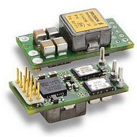
DC/DC Converters & Regulators 66W 4.5-14V OUT 20A 25.65x12.9x8.22 mm
Manufacturer
Ericsson Power Modules
Series
BMR 450r
Datasheet
1.BMR4500002020.pdf
(31 pages)
Specifications of BMR4500002/020
Output Power
110 W
Input Voltage Range
4.5 V to 14 V
Number Of Outputs
1
Output Voltage (channel 1)
0.6 V to 5.5 V
Output Current (channel 1)
20 A
Package / Case Size
25.65 mm x 12.9 mm x 8.2 mm
Output Voltage
0.6 V to 5.5 V
Product
Non-Isolated / POL
Lead Free Status / RoHS Status
Lead free / RoHS Compliant


Definition of reference temperature T
The reference temperature is used to monitor the temperature
limits of the product. Temperature above maximum T
meassured at the reference point P1 are not allowed and may
cause degradation or permanent damage to the product. T
also used to define the temperature range for normal operating
conditions. T
safety margins, proper operation and high reliability ot the
product.
Power Management Overview
The product incorporates a wide range of monitorable and
configurable power management features that are simple to
implement with a minimum of external components.
Additionally, the product includes protection features that
continuously safeguard the load from damage due to
unexpected system faults. A fault is also shown as an alert on
the SALERT pin. The following product parameters can
continuously be monitored by a host: Input voltage, output
voltage/current, and internal temperature. If the monitoring is
not needed it can be disabled and the module enters a low
power mode reducing the power consumption. The protection
features are not affected.
All power management functions can be configured via the
PMBus interface. Monitoring parameters can be pre-
configured to provide alerts for specific conditions. Please
contact your local Ericsson Power Modules representative for
design support of custom configurations or appropriate SW
tools for design and down-load of new configurations.
Efficiency Optimized Dead Time Control
The regulator utilizes a closed loop algorithm to optimize the
dead-time applied between the gate drive signals for the
switch and synch FETs. The algorithm constantly adjusts the
deadtime non-overlap to minimize the duty cycle, thus
maximizing efficiency. This algorithm will null out deadtime
differences due to component variation, temperature and
loading effects. The algorithm can be configured via the
PMBus. Please contact your local Ericsson Power Modules
representative for design support of custom configurations or
appropriate SW tools for design and down-load of new
configurations.
E
Prepared (also subject responsible if other)
EAB/FJB/GMF EKAMAGN
Approved
EAB/FJB/GMF Torbjörn Holmberg
BMR 450 Digital PoL Regulators
Input 4.5-14 V, Output up to 20 A / 100 W
P1
is defined by the design and used to guarantee
P1
Checked
ETORHOL
P1
,
P1
is
Connections
Pin layout, top view.
Ericsson Internal
PRODUCT SPECIFICATION
No.
30/1301-BMR 450 0002 Uen
Date
2010-03-02
Pin
1A
2A
3A
4A
4B
5A
5B
6A
6B
7A
7B
8A
8B
Designation
VIN
GND
VOUT
+S
−S
SA0
SA1
SCL
SDA
FLEX
DGND
SALERT
CTRL
Technical Specification
EN/LZT 146 400 R3A March 2010
© Ericsson AB
Rev
H
Reference
Function
Input Voltage
Power Ground
Output Voltage
Positive sense
Negative sense
Address pin 0
Address pin 1
PMBus Clock
PMBus Data
Analog voltage adjust /
Synchronization
PMBus Ground
PMBus Alert
PMBus Control
(Remote Control)
5 (7)
22
Related parts for BMR4500002/020
Image
Part Number
Description
Manufacturer
Datasheet
Request
R

Part Number:
Description:
37.5-150W DC/DC POWER MODULES
Manufacturer:
Ericsson Power Modules
Part Number:
Description:
DC/DC Power Supply Dual-OUT 3.3V/5V 9.6A/6.4A 40W 10-Pin
Manufacturer:
Ericsson Power Modules
Part Number:
Description:
DC/DC Power Supply Single-OUT 3.3V 20A 66W 8-Pin Quarter-Brick
Manufacturer:
Ericsson Power Modules
Datasheet:
Part Number:
Description:
DC/DC Power Supply Single-OUT 1.8V 50A 90W 11-Pin
Manufacturer:
Ericsson Power Modules
Part Number:
Description:
Module DC-DC 1-OUT 1.8V 30A 54W 9-Pin
Manufacturer:
Ericsson Power Modules

Part Number:
Description:
Module DC-DC 1-OUT 1.8V 60A 108W 11-Pin Half-Brick
Manufacturer:
Ericsson Power Modules
Datasheet:

Part Number:
Description:
Module DC-DC 1-OUT 12V 25A 300W 11-Pin Half-Brick
Manufacturer:
Ericsson Power Modules
Part Number:
Description:
Module DC-DC 1-OUT 5V 20A 100W Quarter-Brick
Manufacturer:
Ericsson Power Modules

Part Number:
Description:
Module DC-DC 1-OUT 12V 6A 72W 8-Pin 1/8-Brick
Manufacturer:
Ericsson Power Modules
Datasheet:
Part Number:
Description:
Module DC-DC 1-OUT 5.05V 2A 10W 18-Pin SMD
Manufacturer:
Ericsson Power Modules
Part Number:
Description:
Manufacturer:
Ericsson Power Modules
Datasheet:

Part Number:
Description:
Module DC-DC 1-OUT 5V 60A 300W 11-Pin Half-Brick Tray
Manufacturer:
Ericsson Power Modules
Part Number:
Description:
Module DC-DC 1-OUT 12V 1A 12W 18-Pin
Manufacturer:
Ericsson Power Modules
Datasheet:
Part Number:
Description:
Module DC-DC 2-OUT 12V/-12V 0.25A 6W 18-Pin SMD
Manufacturer:
Ericsson Power Modules
Part Number:
Description:
Module DC-DC 1-OUT 28V 11A 310W 11-Pin Half-Brick Tray
Manufacturer:
Ericsson Power Modules
Datasheet: