BMR4500002/020 Ericsson Power Modules, BMR4500002/020 Datasheet - Page 21
BMR4500002/020
Manufacturer Part Number
BMR4500002/020
Description
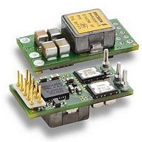
DC/DC Converters & Regulators 66W 4.5-14V OUT 20A 25.65x12.9x8.22 mm
Manufacturer
Ericsson Power Modules
Series
BMR 450r
Datasheet
1.BMR4500002020.pdf
(31 pages)
Specifications of BMR4500002/020
Output Power
110 W
Input Voltage Range
4.5 V to 14 V
Number Of Outputs
1
Output Voltage (channel 1)
0.6 V to 5.5 V
Output Current (channel 1)
20 A
Package / Case Size
25.65 mm x 12.9 mm x 8.2 mm
Output Voltage
0.6 V to 5.5 V
Product
Non-Isolated / POL
Lead Free Status / RoHS Status
Lead free / RoHS Compliant


within 20 ms in default configuration using remote control.
When starting by applying input voltage the control circuit boot-
up time adds an additional 10 ms delay. The soft-start power
up of the product can be reconfigured using the PMBus
interface. Please contact your local Ericsson Power Modules
representative for design support of custom configurations or
appropriate SW tools for design and down-load of new
configurations.
Output Voltage Sequencing
A group of regulators may be configured to power up in a
predetermined sequence. This feature is especially useful
when powering advanced processors, FPGAs, and ASICs that
require one supply to reach its operating voltage prior to
another supply reaching its operating voltage. Multi-regulator
sequencing can be achieved by configuring each device start
delay and rise time through the PMBus and use the same
remote control start signal. Please contact your local Ericsson
Power Modules representative for design support of custom
configurations or appropriate SW tools for design and down-
load of new configurations.
Voltage Margining Up/Down
The regulator can momentarily adjust its output higher or lower
than its nominal voltage setting in order to determine whether
the load device is capable of operating over its specified supply
voltage range. This provides a convenient method for
dynamically testing the operation of the load circuit over its
supply margin or range. It can also be used to verify the
function of supply voltage supervisors. Margin limits of the
nominal output voltage ±5% are default, but the margin limits
can be reconfigured using the PMBus interface to as high as
10% or as low as 0V. Please contact your local Ericsson Power
Modules representative for design support of custom
configurations or appropriate SW tools for design and down-
load of new configurations.
Pre-Bias Startup Capability
Pre-bias startup often occurs in complex digital systems when
current from another power source is fed back through a dual-
supply logic component, such as FPGAs or ASICs. The BMR
450 product family incorporates synchronous rectifiers, but will
not sink current during startup, or turn off, or whenever a fault
shuts down the product in a pre-bias condition. Please contact
your local Ericsson Power Modules representative for design
support of custom configurations or appropriate SW tools for
design and down-load of new configurations.
I
The setup time, t
before the rising edge of the clock signal, SCL. The hold time
t
the clock signal, SCL. If these times are violated incorrect data
can be captured or meta-stability can occur and the bus
communication fails.
E
2
hold
Prepared (also subject responsible if other)
EAB/FJB/GMF EKAMAGN
Approved
EAB/FJB/GMF Torbjörn Holmberg
BMR 450 Digital PoL Regulators
Input 4.5-14 V, Output up to 20 A / 100 W
C/SMBus Setup and Hold Times – Definitions
, is the time the data must be stable after the rising edge of
set
, is the time the data, SDA, must be stable
Checked
ETORHOL
SMBus timing diagram
Thermal Consideration
General
The regulators are designed to operate in different thermal
environments and sufficient cooling must be provided to
ensure reliable operation.
Cooling is achieved mainly by conduction, from the pins to the
host board, and convection, which is dependant on the airflow
across the regulator. Increased airflow enhances the cooling of
the regulator.
The Output Current Derating graph found in the Output section
for each model provides the available output current vs.
ambient air temperature and air velocity at specified V
The products with an output power of
254 x 254 mm, 35 µm (1 oz), 16-layer test board, and for
output power of
layer test board are used. The test board is mounted vertically
in a wind tunnel with a cross-section of 608 x 203 mm.
Proper cooling of the product can be verified by measuring the
temperature at positions P1 and P2. The temperature at these
positions should not exceed the max values provided in the
table below.
Note that the max value is the absolute maximum rating
(non destruction) and that the electrical Output data is
guaranteed up to T
See Design Note 019 for further information.
Temperature positions and air flow direction.
Ericsson Internal
PRODUCT SPECIFICATION
No.
30/1301-BMR 450 0002 Uen
Date
2010-03-02
Position Device
P1
P2
Top view
Reference point, L1, inductor T
N1, control circuit
P1
<
100
Technical Specification
P1
EN/LZT 146 400 R3A March 2010
© Ericsson AB
Rev
H
AIR FLOW
+85°C.
W a 254 x 254 mm, 35 µm (1 oz), 8-
Reference
Designation
T
P1
P2
≥
100
Bottom view
P2
W are tested on a
max value
120º C
120º C
I
.
4 (7)
21
Related parts for BMR4500002/020
Image
Part Number
Description
Manufacturer
Datasheet
Request
R

Part Number:
Description:
37.5-150W DC/DC POWER MODULES
Manufacturer:
Ericsson Power Modules
Part Number:
Description:
DC/DC Power Supply Dual-OUT 3.3V/5V 9.6A/6.4A 40W 10-Pin
Manufacturer:
Ericsson Power Modules
Part Number:
Description:
DC/DC Power Supply Single-OUT 3.3V 20A 66W 8-Pin Quarter-Brick
Manufacturer:
Ericsson Power Modules
Datasheet:
Part Number:
Description:
DC/DC Power Supply Single-OUT 1.8V 50A 90W 11-Pin
Manufacturer:
Ericsson Power Modules
Part Number:
Description:
Module DC-DC 1-OUT 1.8V 30A 54W 9-Pin
Manufacturer:
Ericsson Power Modules

Part Number:
Description:
Module DC-DC 1-OUT 1.8V 60A 108W 11-Pin Half-Brick
Manufacturer:
Ericsson Power Modules
Datasheet:

Part Number:
Description:
Module DC-DC 1-OUT 12V 25A 300W 11-Pin Half-Brick
Manufacturer:
Ericsson Power Modules
Part Number:
Description:
Module DC-DC 1-OUT 5V 20A 100W Quarter-Brick
Manufacturer:
Ericsson Power Modules

Part Number:
Description:
Module DC-DC 1-OUT 12V 6A 72W 8-Pin 1/8-Brick
Manufacturer:
Ericsson Power Modules
Datasheet:
Part Number:
Description:
Module DC-DC 1-OUT 5.05V 2A 10W 18-Pin SMD
Manufacturer:
Ericsson Power Modules
Part Number:
Description:
Manufacturer:
Ericsson Power Modules
Datasheet:

Part Number:
Description:
Module DC-DC 1-OUT 5V 60A 300W 11-Pin Half-Brick Tray
Manufacturer:
Ericsson Power Modules
Part Number:
Description:
Module DC-DC 1-OUT 12V 1A 12W 18-Pin
Manufacturer:
Ericsson Power Modules
Datasheet:
Part Number:
Description:
Module DC-DC 2-OUT 12V/-12V 0.25A 6W 18-Pin SMD
Manufacturer:
Ericsson Power Modules
Part Number:
Description:
Module DC-DC 1-OUT 28V 11A 310W 11-Pin Half-Brick Tray
Manufacturer:
Ericsson Power Modules
Datasheet: