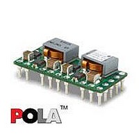
PMN5118UP Ericsson Power Modules, PMN5118UP Datasheet - Page 32

PMN5118UP
Manufacturer Part Number
PMN5118UP
Description
DC/DC Converters & Regulators 0.7-3.6V 30A Non-Iso Input 4.5-5.5V 108W
Manufacturer
Ericsson Power Modules
Series
PMNr
Datasheet
1.PMN5118USR.pdf
(37 pages)
Specifications of PMN5118UP
Output Power
108 W
Input Voltage Range
4.5 V to 5.5 V
Number Of Outputs
1
Output Voltage (channel 1)
0.7 V to 3.6 V
Output Current (channel 1)
30 A
Output Type
POLA Non-Isolated Regulator
Product
Non-Isolated / POL
Lead Free Status / RoHS Status
Lead free / RoHS Compliant
Available stocks
Company
Part Number
Manufacturer
Quantity
Price
Part Number:
PMN5118UP
Manufacturer:
ERICSSON/爱立信
Quantity:
20 000
E
7
8
9
10
11
12
13
Prepared (also subject responsible if other)
EYIPYAN
Approved
SEC/D (Julia You)
PMN 5000 series
POL regulator, Input 4.5-5.5 V, Output up to 30 A/108 W
GND
GND
V
+Sense
-Sense
V
Turbo Trans This input pin adjusts the transient
o
o
Adjust
This is the common ground connection
for the V
also the 0 V
inputs.
This is the common ground connection
for the V
also the 0 V
inputs.
The regulated positive power output with
respect to the GND.
The sense input allows the regulation
circuit to compensate for voltage drop
between the module and the load. For
optimal voltage accuracy, +Sense must
be connect V
The sense input allows the regulation
circuit to compensate for voltage drop
between the module and the load. For
optimal voltage accuracy, -Sense must
be connect GND(pin 8) , very close to the
load.
A 0.1 W 1% resistor must be directly
connected between this pin and pin 8
(GND) to set the output voltage to a value
higher than 0.7 V. The temperature
stability of the resistor should be 100
ppm/℃ (or better). The setpoint range for
the output voltage is from 0.7V to 3.6V. If
left open circuit, the output voltage
defaults to its lowest value. For further
information, on output voltage adjustment
see the related application note. The
specification table gives the preferred
resistor values for a number of standard
output voltages.
response of the regulator. To activate the
Turbo Trans
resistor must be connected between this
pin and pin 10 (+Sense) very close to the
module. For a given value of output
capacitance, a reduction in peak output
voltage deviation is achieved by using
this feature. If unused, this pin must be
left open-circuit. External capacitance
must never be connected to this pin. The
resistance requirement can be selected
from the Turbo Trans
the Application Information section.
I
I
and V
and V
dc
dc
TM
o
reference for the control
reference for the control
, very close to the load.
feature, a 1%, 50mW
o
o
power connections. It is
power connections. It is
TM
resistor table in
Checked
EQUENXU
Ericsson Internal
PRODUCT SPECIFICATION
No.
3/1301-BMR656 5118 Uen
Date
2007-7-9
14
Track
Technical Specification
EN/LZT 146 386 R1A
© Ericsson Power Modules AB
Rev
B
This is an analog control input that
enables the output voltage to follow an
external voltage. This pin becomes active
typically 20 ms after the input voltage has
been applied, and allows direct control of
the output voltage from 0 V up to the
nominal set-point voltage. Within the
control voltage is raised above this range,
the module regulates at its set-point
voltage. The features allows the output
voltage to rise simultaneously with other
modules powered from the same input
bus. If unused, this input should be
connected to V
NOTE: Due to the undervoltage lockout
feature, the output of the module cannot
follow its own input voltage during power
up. For more information, see the related
application note.
Reference
I
.
July 2007
7 (8)
32


